 |
|||
|
|
|||
|
|
|||
| ||||||||||
|
|
 5.
If previous Steps 1 thru 5
check satisfactorily, check Delcotron
alternator as follow:
a.
Disconnect Energizer ground
cable.
Connect an ammeter in the
b.
circuit at the "ABT" terminal
of the alternator.
c.
Reconnect Energizer gound
cable.
Fully load electrical circuit.
d.
Connect a carbon pile across the
Energizer.
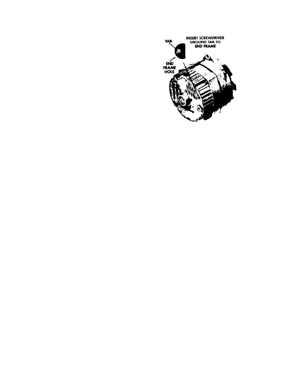
Figure G-Grounding generator field
winding. (Wiring connections not shown.)
Operate engine at moderate
d.
speed as required, and adjust
If output is not within 10 per-
j.
carbon pile as required, to ob-
center of rated output, check the
tain maximum current output.
field winding, diode trio, rectifier
bridge, and stator as covered in
f.
If ampere output is within
"Alternator Repair" section.
10 percent of rated output as
stamped on alternator frame,
from Alternator
k.
Remove ammeter
alternator is not defective;
and turn accessories off.
recheck Steps 1 thru 5.
If ampere output is not within
g.
10 percent of rated output, ground
B.
OVERCHARGED ENERGIZER
the field winding by inserting a
screwdriver into the test hole
1.
Connect a voltmeter from alternator
(Fig. 6).
No. 2 terminal to ground.
If reading is
zero, No. 2 lead circuit is open.
CAUTION
2.
If Energizer and No. 2 lead circuit
Tab is within 3/4 inch of casting
check good, but an obvious overcharge
Do not force screwdriver
surface.
condition exists as evidenced by excessive
deepter than one inch into end frame.
Energizer water usage proceed as follows:
Operate engine at moderate speed
h.
a.
Separate end frames as covered in
as required, and adjust carbon pile
"Disassembly" s e c t i o n u n d e r h e a d i n g o f
as required to obtain maximum current
"Alternator Repair".
output.
Check field winding for shorts. If
If output is within 10 percent of
1.
shorted replace rotor and regulator.
rated output replace regulator as
covered in "Alternator Repair" sec-
b.
Connect ohmeter using lowerst
tion, and check field winding.
range scale from brush lead clip to
end frame as shown in Step 1, Fig. 8,
then reverse lead connections.
5-50
|
|
Privacy Statement - Press Release - Copyright Information. - Contact Us |
