 |
|||
|
|
|||
|
|
|||
| ||||||||||
|
|
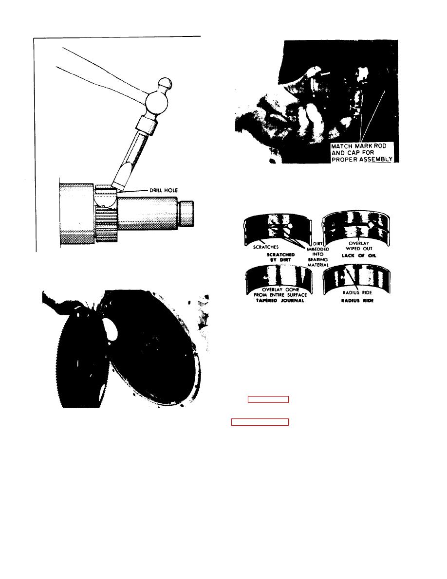 Figure 5-49. Cap and Bearing Removal
Figure 5-47. Crankshaft Gear Removal
Figure 5-50. Bearing Inspection
j. To split the gear, first drill a hole of
approximately l/4 inch diameter lengthwise of the
gear and between the keyway and the teeth. After
drilling, a light blow with a cold chisel will spread
the gear a few thousandths and permit removal.
See figure 5-47.
k.
Remove the flywheel as shown in
Figure 5-48. Flywheel Removal
1.
When removing the flywheel, mark the
crankshaft flange and flywheel as they
i. In those instances where replacement of the
will reassembly in one position.
crankshaft gear is necessary and a puller is not
available or the gear is too tight, it will be
m.
To remove bell housing, remove
necessary to split the gear.
retainer and pull housing from engine
assembly.
Remove rear main seal from
housing by tapping aroung edge of seal
with drift & hammer.
5-34
|
|
Privacy Statement - Press Release - Copyright Information. - Contact Us |
