 |
|||
|
|
|||
|
Page Title:
Figure 5-34. Removing Crankshaft PulIey Nut |
|
||
| ||||||||||
|
|
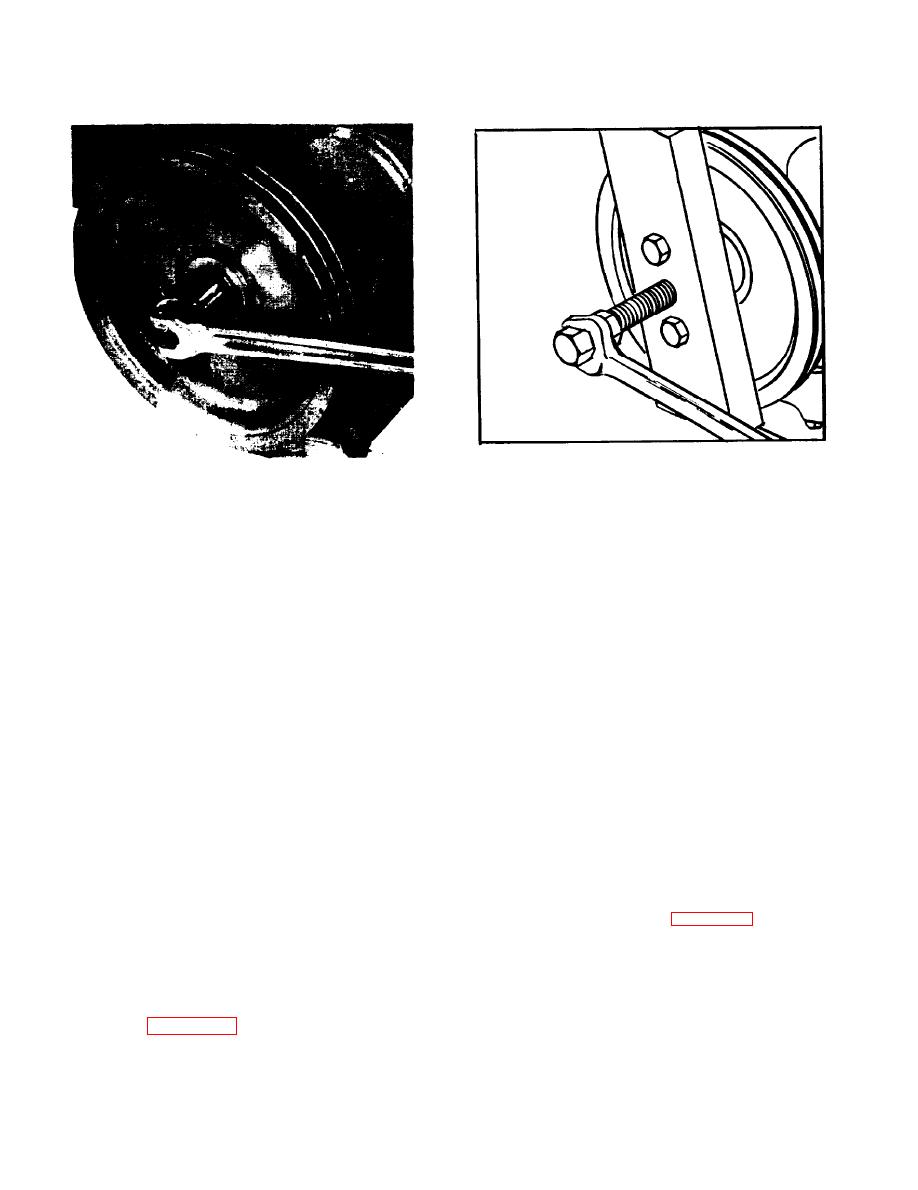 Figure 5-35. Pulley Removal
Figure 5-34. Removing Crankshaft PulIey Nut
LEGEND FOR FIGURE 5-36
1.
Seal
11.
L.W.
Bolt,
21.
Dowell
31.
Shaft
2.
Oil Lube
12.
Bolt,
L.W
22.
Plate
32.
Bolt, L.W.
3.
Fitting
13.
Bolt,
L.W.
23.
Retainer
33.
Bolt
4.
Fitting
14.
L.W.
Bolt,
24.
Gasket
34.
Bolt, L.W.
5.
Bolt
15.
L.W.
Bolt,
25.
Snap Ring
35.
Bolt, L.W.
6.
Bolt, L.W.
16.
Bolt,
L.W.
26.
Washer
36.
Bolt, L.W.
7.
Bolt, L.W.
17.
DoWel
27.
Idler Gear
37.
Bolt
8.
Bolt, L.W.
18.
L.W.
Bolt,
28.
Bushing
38.
Plate
9.
Bolt, L.W.
19.
Bolt,
L.W.
29.
Washer
39.
Gasket
10.
Dowell
20.
Cover
30.
Spacer
down in this manner, cylinder sleeve will be pushed
IV for proper belt tension and adjustment
out by upward travel of the piston.
procedure.
b. Remove the crankshaft pulley nut by blocking
d. Install cooling fan,
the flywheel with a piece of wood or soft bar stock
to prevent crankshaft motion, and removing pulley
nut with wrench as shown in figure 5-34.
e. Refill cooling system with clean water or
water-antifreeze solution.
c. Using a bar type puller, remove the
When using the puller, be
pulley.
5-40. TIMING GEARS AND CAMSHAFT
carefull not to damage the threaded end
REMOVAL.
of the crankshaft.
a Refer to figure 5-33 and install cylinder sleeve
d. Inspect the crankshaft pulley wear
locks as shown in the illustration. If not locked
sleeve. The wear sleeve provides a re-
placeable running surface for the front
5-28
|
|
Privacy Statement - Press Release - Copyright Information. - Contact Us |
