 |
|||
|
|
|||
|
Page Title:
Figure 5-29. Rocker Arm Retainer |
|
||
| ||||||||||
|
|
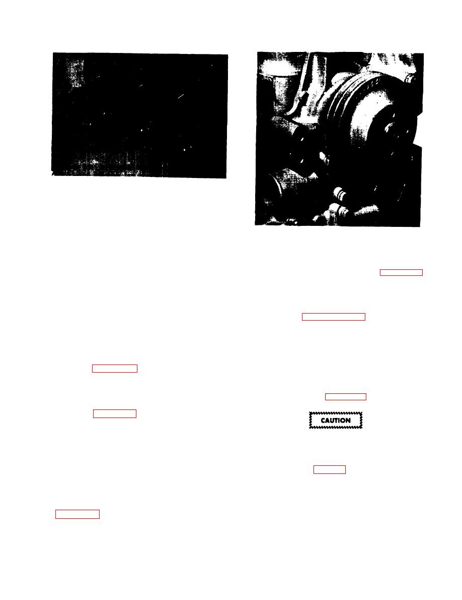 Figure 5-29. Rocker Arm Retainer
b. Be sure that the refacer grinding wheels are
properly dressed and are the proper wheels for the
Figure 5-30. Captive Water Pump Bolt
valve material (exhaust valves are Stellite faced).
c. Remove only enough stock to correct the
runout or to remove pits and grooves. Care must be
clip is properly in place as shown by figure 5-29.
exercised so that the entire Stellite facing is not
removed.(Stellite facing is .040" min.
5-35. CYLINDER HEAD REASSEMBLY
depth)
AND INSTALLATION.
d. If the edge of the valve head is less than l/32
inch after refacing, replace the valve as it will run
a. Refer to figure
5-15 and install the
too hot in the engine.
components of the cylinder head assembly as
s h o w n by the illustration. Do not install rocker
5-34. ROCKER ARM DISASSEMBLY
arm assembly at this time.
AND REPAIR.
b. Install new head gasket into position.
a. Refer to figure 5-29 and remove retainer clip
as shown by arrow.
c. Install the cylinder head and head bolts.
Torque bolts to specifications and in proper
b. Slide parts off shaft, number rocker arms as
sequence as shown in figure 4-40.
they are removed for reassembly in same order as
removed. See figure 5-15 for exploded view.
c. Check for wear and broken parts, clean,
The No. 9 head bolt is a special retainer
making sure all oil passages are clear of dirt, varnish
and gum deposits.
drilled for passage of oil and will require
less torque than the other retainers (see
d. Rocker arms cannot be rebushed and must be
Specifications, Table 5).
replaced is the bushing surface is excessively worn
or is otherwise unfit for further service.
d. Install push rods, installing each rod into the
same socket from which it was removed. Replace
e. Reassemble the rocker arm assembly as shown
in figure 5-15, and make certain that the retainer
bent or worn push rods with new ones.
5-25
|
|
Privacy Statement - Press Release - Copyright Information. - Contact Us |
