 |
|||
|
|
|||
|
Page Title:
Figure 5-26. Scrap Valve Welded In Place |
|
||
| ||||||||||
|
|
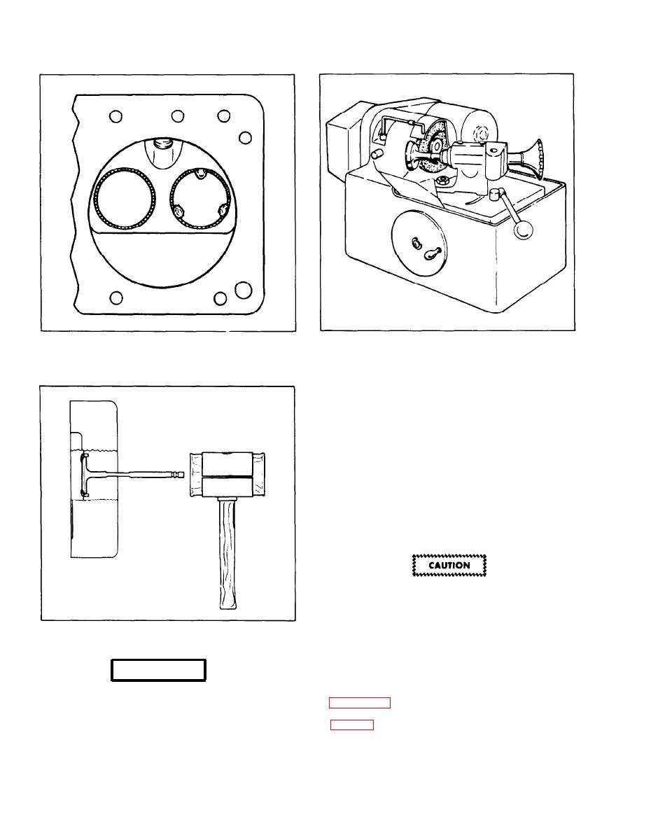 Figure 5-26. Scrap Valve Welded In Place
Figure 5-28. Valve Grinding Machine
cause serious freezing. Use gloves and
forceps or bent wire to remove metal parts.
Never touch metal that has been in dry ice
until temperature has risen above the
freezing point.
m. Using a pair of forceps or a hooked wire (see
warning), quickly lift the chilled insert from the
dry ice and locate it over the counterbore so the
lower edge is entered squarely. Start the driving
tool pilot in the valve guide, bringing the driving
face against the insert upper surface accurately,
and tap the tool with a medium weight hammer.
If severe hammering seems to be required,
the counterbore is not clean or has burrs,
t h e insert is not chilled enough, or not
Figure 5-27. Driving Out Seat
started into the counterbore straight and
true.
WARNING
5-33. VALVE GRINDING (Refacing).
a. A valve grinding device similar to that shown
in figure 5-28 will be required to reface the valves
Dry ice is a solid with an extreme low
at the proper angle according to the specifications
t e m p e r a t u r e . Contact with the skin will
of Table 5.
5-24
|
|
Privacy Statement - Press Release - Copyright Information. - Contact Us |
