 |
|||
|
|
|||
|
Page Title:
Figure 5-18. Testing Valve Spring |
|
||
| ||||||||||
|
|
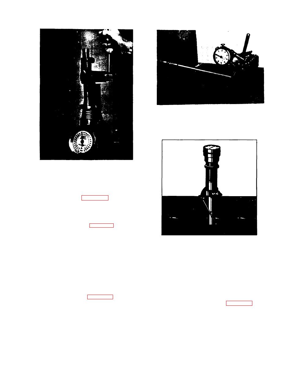 Figure 5-19. Checking Valve Face Runout
Figure 5-18. Testing Valve Spring
f. Check cylinder head for flatness by placing a
straightedge across cylinder head in several
directions as shown in figure 5-21, and measuring
gaps under straightedge with feeler gage. Cylinder
head must be flat within 0.005 inch.
g . Clean valve guides using electric drill and
carbon cutter as shown in figure 5-22. Check valve
guides against specifications of Table 5 to
determine if they must be replaced.
5-31. VALVE GUIDE REPLACEMENT. If valve
Figure 5-20. Checking Valve Seat Runout
guides are worn oversize, they must be replaced as
press. DO NOT DRIVE GUIDE INTO PLACE
follows:
USING A HAMMER; DAMAGE TO GUIDE WILL
a. The old valve guide may be removed by driving
RESULT IN DOING SO. Make sure guide is
guide from head using an appropriate driving tool.
extended above head as specified in Specifications
of Table 5.
b. To insert the new guide, select an installation
d. Ream valve guide only if necessary to remove
high spots and burrs by the use of a valve guide
tool of correct size to prevent damage to the guide,
r e a m e r (high spots sometimes occur when new
and position in place. See figure 5-23.
guides are pressed in head). See figure 5-24.
c . Press guide into place using an appropriate
5-21
|
|
Privacy Statement - Press Release - Copyright Information. - Contact Us |
