 |
|||
|
|
|||
|
Page Title:
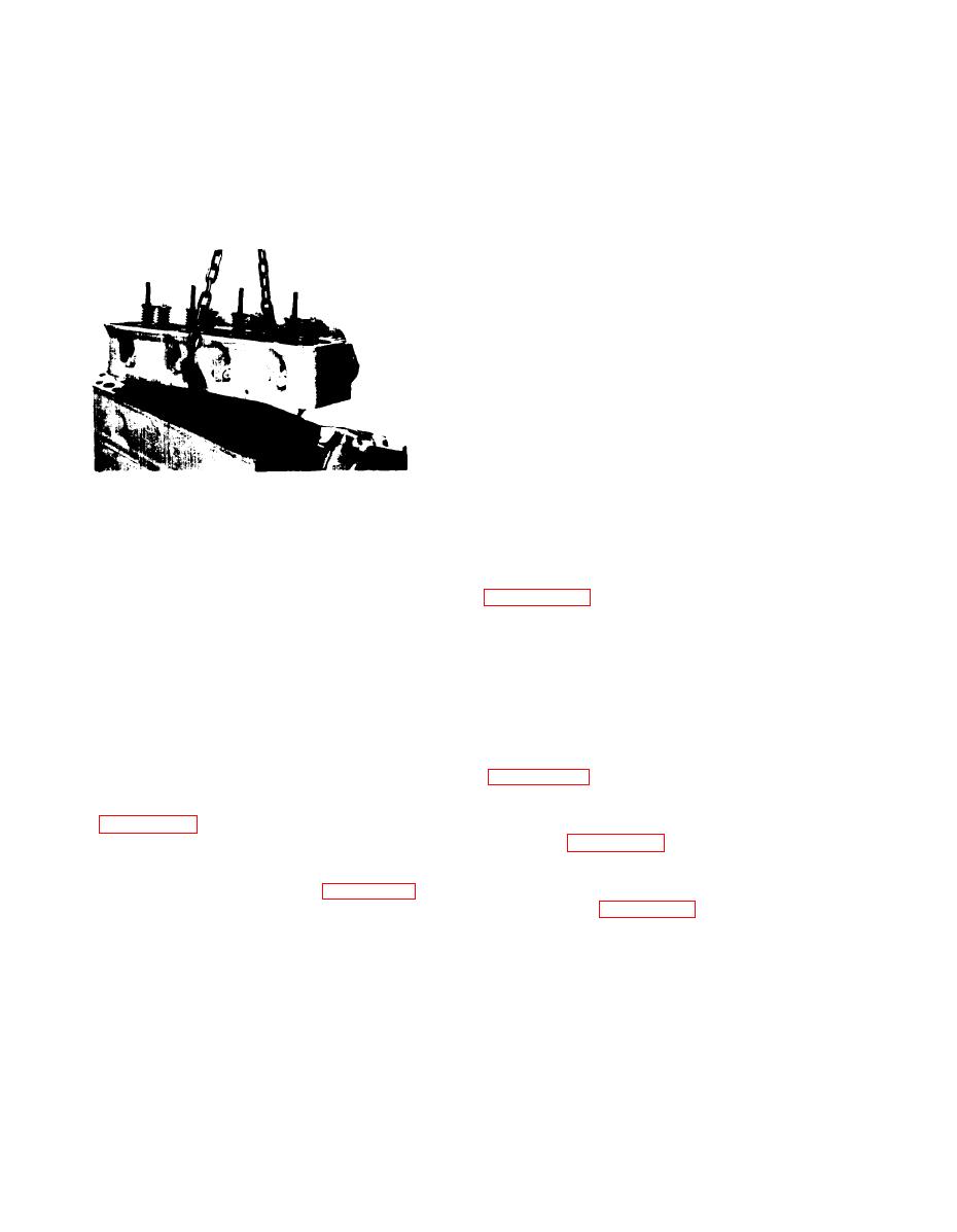
Figure 5-14. Cylinder Head Removal |
|
||
| ||||||||||
|
|
 LEGEND FIGURE 5-15
21. cup
l.Gasket set
22. Lock
2. Lifter
23. Lock
3. Gear
24. Rotator
4. Plunger, spring
25. Seat
6. Bushing
26. Retainer
7. Key
27. Spring
8. camshaft
28. Spring
9. Push rod
29. Seal
10. Adjuster
30. Guide
11. Rocker arm assembly
31. Guide
12. Rocker arm assembly
32. Seat
13. washer
33. Valve. exhaust
14. Hair pin
34. Value intake
15. cap
35. Head
17. Pivot
36. Plug-expansion
18. spring
37. Head
19. support
assembly
20. Stud, nut, washer
Figure 5-14. Cylinder Head Removal
1 . A t t a c h lifting eyes and remove
5-28.
REMOVAL
c y l i n d e r head (with manifolds attached)
a . Remove water outlet assembly before
f r o m the cylinder block as shown in
loosening cylinder head bolts. This pre-
vents cracking of the water outlet casting.
NOTE
b . Remove water outlet bolts and mark
I t may be necessary to tap the
them for proper position, as the bolts
c y l i n d e r head sharply with a
vary in length.
fibre hammer a few times to
b r e a k the cylinder head gasket
c . Check water outlet casting for
seal.
cracks.
5-29. DISASSEMBLY Cylinder head dis-
d . Remove the rocker arm assembly, noting
a s s e m b l y is outlined below. R e f e r t o
t h e l e n g t h o f t h e r e t a i n i n g b o l t s . Do not
Figure 5-15 for general parts iden-
mix these bolts with any others as bolts of
tification.
t h e proper length must be used at reassembly.
S e e Figure 5-12 for rocker arm removal.
a . U s i n g valve spring compressor as
s h o w n in Figure 5-16, compress the valve
e . Number all pushrods so that they must
s p r i n g s , r e m o v e spring locks . . . release
be reinstalled in same location, and re-
spring compressor and remove . . . rotator
m o v e all pushrods as shown in Figure 5-13.
(exhaust) seat (intake), spring and spring
pilot.
See Figure 5-17 for valve parts
f . C h e c k for bent or broken push rods.
removed.
Replace bent or broken rods . . . Do Not
attempt to straighten or repair.
b . C h e c k valve stem for burrs and re-
m o v e before trying to take valve from
g . D i s c o n n e c t spring and linkage between
g u i d e (burrs will damage valve guide).
g o v e r n o r and carburetor, and remove carbure-
t o r from intake manifold.
c . R e m o v e all parts of intake and ex-
h a u s t valves in order. Mark valves and parts
and store together for installation in same
R e m o v e cylinder head bolts.
h.
o r d e r and relationship as removed
5-18
|
|
Privacy Statement - Press Release - Copyright Information. - Contact Us |
