 |
|||
|
|
|||
|
Page Title:
Figure 4-89. Checking Roller Angle |
|
||
| ||||||||||
|
|
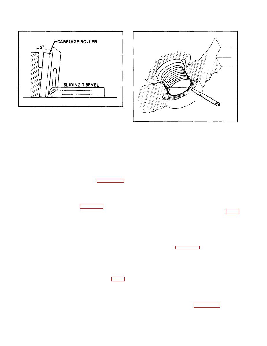 Figure 4-89. Checking Roller Angle
are in place, raise inner rail enough to install the
Figure 4-90. Securing Outer Thrust Roller
stop block behind the inner rail.
d. Span upper carriage rollers
4-84. CARRIAGE ROLLER ADJUSTMENT.
c h e c k i n g across the upper outside of the
Carriage roller adjustment will require removal of
roller (outermost camber point). Add or subtract
the carriage. Refer to paragraph 5-140 for
s h i m s behind rollers until the span across the
carriage removal procedures.
rollers is equal to the inner rail span, less l/16 inch
total. The l/16 inch clearance must not be
4-86. TOOLS REQUIRED. Special measuring
e x c e e d e d . No more than l/32 inch clearance is
devices called spanners are required to perform the
permissible over the roller on each side.
carriage roller adjustments. Refer to figures 4-87
and 4-88 for details of construction.
4-87. CENTERING ADJUSTMENT.
4-86. CLEARANCE ADJUSTMENT.
a. Check outer thrust rollers for wear and loose
mounting studs. If bearings are worn, replace, If
a. Use inside spanning tool, figure 4-87, to check
loose, tighten and stake in place as shown in figure
the distance between the inner rails at every ten
4-90.
inches over their entire length. Lock the tool at the
smallest span obtained.
b . Center the carriage roller within the outer
t h r u s t rollers by placing a 6-inch scale on the
Note
carriage roller surface and measuring the distance
to the outer thrust roller face. Check this distance
Measurements must be taken inside the
on both sides. (See figure 491.)
rails, not on the edges, and the spanning
tool must be held perpendicular to the
c. Transfer shim from one side to the other to
rails.
make the measurement equal on both sides. Do not
r e m o v e a shim from one side without replacing
b. Use a sliding "T" bevel to check angle of the
that shim on the opposite side.
carriage rollers. This angle must be 2 1/2. If
not, the roller pin must be replaced. (See figure
4-88. SQUARING ADJUSTMENT.
489.)
a. Check for an out-of-square condition by
c. Set outside spanning tool to match span of the
placing a carpenter's square over the rollers and
inside spanning tool, and lock the outside tool in
upper fork bar as shown in figure 4-92. Hold the
position.
4-62
|
|
Privacy Statement - Press Release - Copyright Information. - Contact Us |
