 |
|||
|
|
|||
|
Page Title:
Figure 4-17. Element Retainer Nuts |
|
||
| ||||||||||
|
|
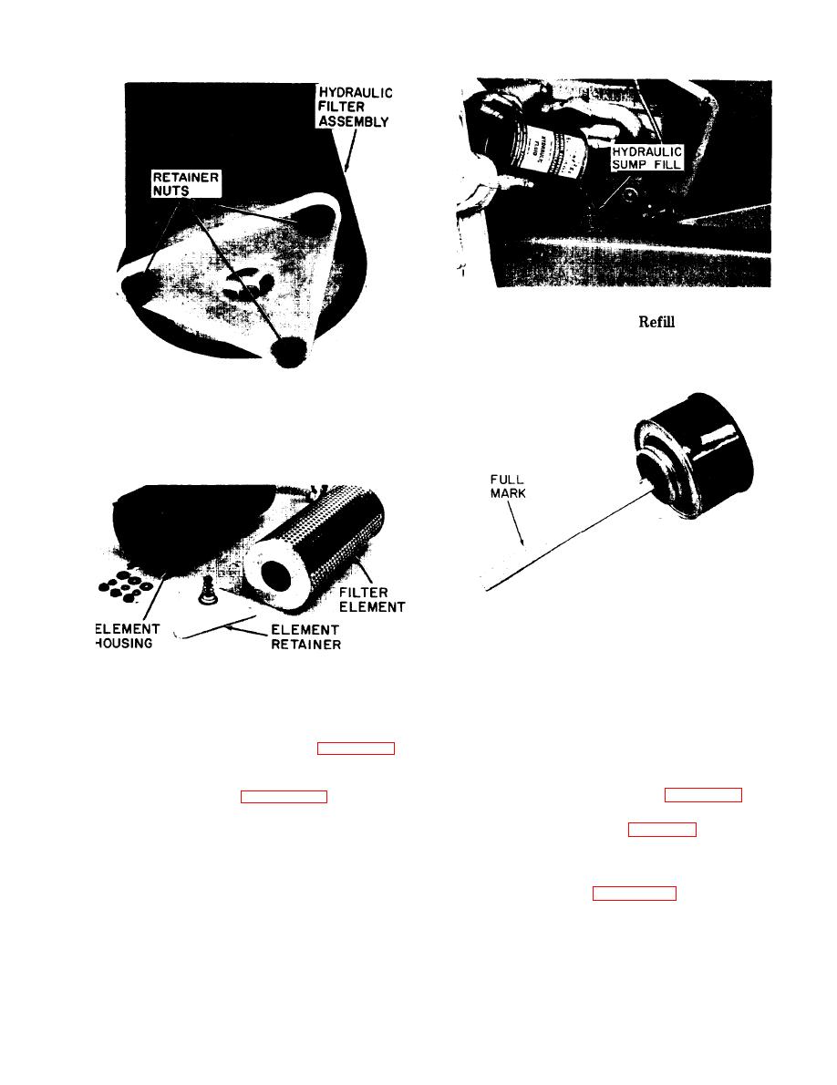 Figure 4-19. Sump Tank
Procedure
Figure 4-17. Element Retainer Nuts
Figure 4-20. Sump Breather Dipstick
Figure 4-18. Filter Disassembled
retainer plate and three retainer nuts. Reinstall
filter assembly into sump tank and tighten clamp
on suction pipe.
k. Remove the three filter element retainer nuts
from the retainer plate as shown in figure 4-17.
o. Install sump cover plate, securing with three
nuts on cover studs. Tighten nuts to 7 lb./ft.
1. Separate element retainer, element, and
p. Refill sump tank, as shown in figure 4-19, with
housing as shown in figure 4-18. Discard old
7 - l / 4 gallons of hydraulic fluid per specification
element and clean housing and retainer thoroughly.
shown in lubrication chart, figure 4-1.
m . Install a new filter element, inserting into
q . Start engine and
operate hydraulic controls
housing so that seal on top of element will contact
several times, checking
for leaks. Check oil level on
the closed upper end of housing.
breather dipstick (see
required to bring level
to full mark on dipstick.
n. Secure element in position by installing
4-16
|
|
Privacy Statement - Press Release - Copyright Information. - Contact Us |
