 |
|||
|
|
|||
|
|
|||
| ||||||||||
|
|
 The
reduce arcing and current leakage.
When the engine has obtained normal
distributor features automatic spark
operating temperature the choke valve
advance through the action of centrifugal
(25) must be fully opened to assure
force on the advance weights. The 12
maximum power and economy. In addi-
volt automative type coil is mounted just
tion, extended use of the choke re-
forward of the distributor in a bracket
sults in more gasoline being supplied
attached to the left side of the engine.
to the engine than can be burned. A
large percentage of the unburned gas-
ALTERNATOR. The alternator is a
1-39.
oline is lost through the exhaust
12 volt, 32 ampere unit mounted on an
system. The remainder of the raw
adjusting bracket to the side of the
gasoline is forced between the pistons
engine and driven by a V-belt.
and cylinder walls, washing away the
protective oil film and increasing
engine wear, and enters the crankcase
where it dilutes the engine oil.
Any adjustments that are necessary on
the carburetor should never be attempted
until the engine has obtained its normal
operating temperature and the choke valve
(25) has been placed in the wide open
position.
STARTER MOTOR. The starting motor
1-36.
is bolted to the engine flywheel housing
on the right underside of the vehicle.
The motor is a two pole, four-field, 12
volt unit which cranks the engine when
the pinion drive is engaged to the fly-
wheel ring gear. An electrical inter-
lock prevents starter engagement when
the engine is running.
STARTER SOLENOID. The starter
1-37.
solenoid is bolted to the starter drive
housing and serves two functions; that
of engaging the starter pinion to the
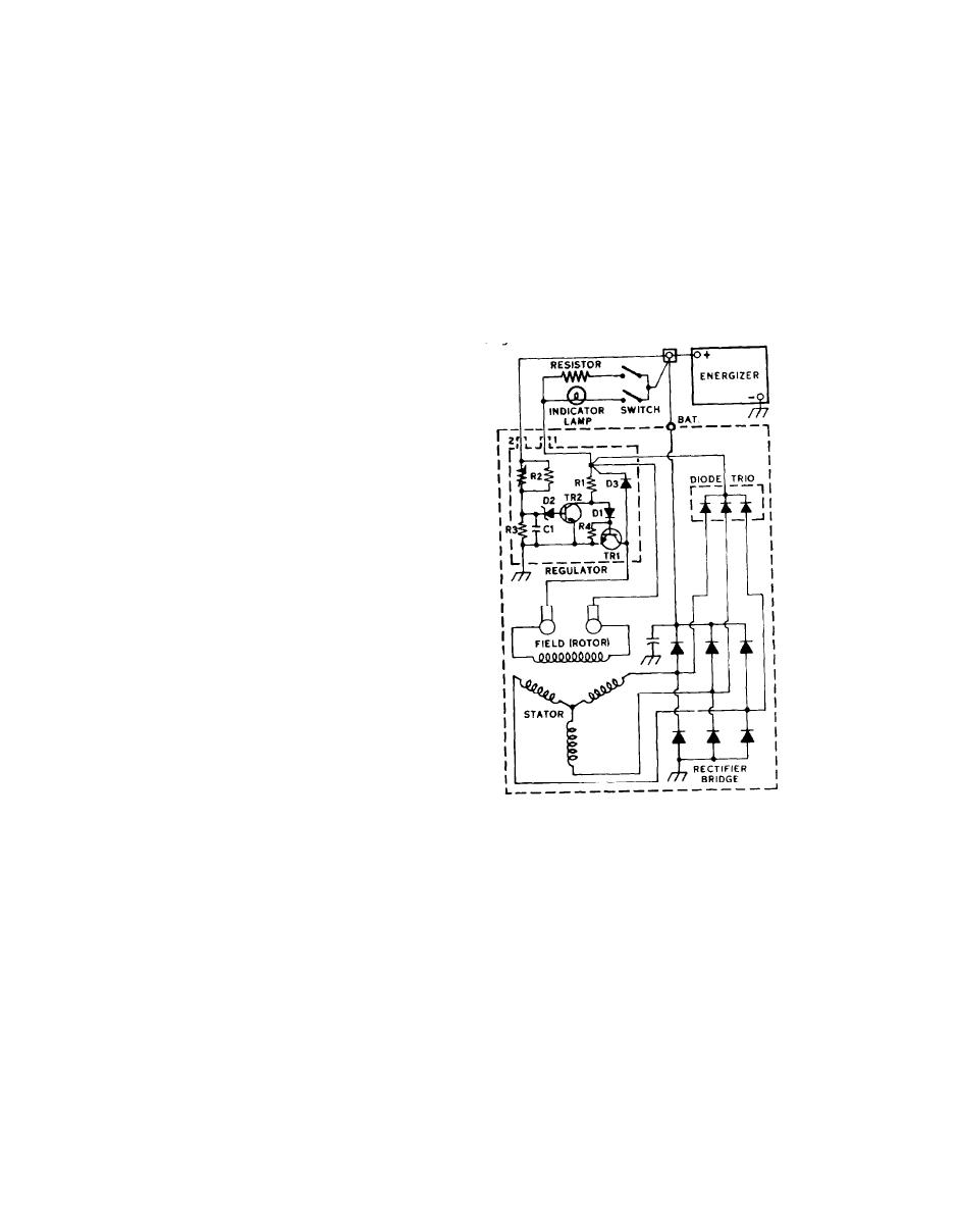
Typical 10-SI Wiring Diagram.
flywheel ring gear, and acts as a
switch to close the circuit between the
Basic principles of operation are as
The solenoid
battery and starter motor.
follows:
becomes energized when the ignition
switch mounted on the dash is held in
When the SWITCH is closed, current from
the start position.
the ENERGIZER follows through the
A M M E T E R and the RESISTOR to the
IGNITION DISTRIBUTOR AND COIL.
1-38.
generator no. 1 terminal (at top of
The single point set 'distributor is
REGULATOR), t h r o u g h r e s i s t o r R 1 , d i o d e
located on the left side of the engine
Dl, and the base emitter of transistor
and is driven by the oil pump shaft.
TR1 to ground, and then back to the
This location provides easy access for
ENERGIZER. The ammeter is then
service. The distributor shaft features
energized. The resistor in parellel
offset drive gear which makes improper
with the ammeter reduces total
assembly impossible. The distributor
circuit resistance to provide higher
cap is molded of an alkyd material to
field current for initial voltage
buildup when the engine starts.
1-18
|
|
Privacy Statement - Press Release - Copyright Information. - Contact Us |
