 |
|||
|
|
|||
|
Page Title:
SERVICE BRAKE AND INCHING CONTROL SYSTEM - continued |
|
||
| ||||||||||
|
|
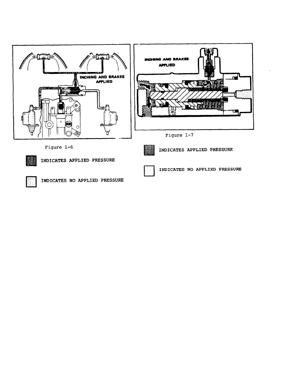 This detail of the selector valve
When the inching pedal is pushed down to a
shows fluid, trapped between the
point where the transmission is partially
brake piston cup and the lockout
disengaged, the brake piston is applied.
piston, being forced out of valve
Fluid, trapped between the brake piston
to start applying brakes during
cup and the lockout piston, then flows
inching operation. (Refer to Fig. 7)
through the residual check valve, and to
the wheel cylinders to start applying the
brakes. (Refer to Fig. 1-6)
1-8
|
|
Privacy Statement - Press Release - Copyright Information. - Contact Us |
