 |
|||
|
|
|||
|
Page Title:
SERVICE BRAKE AND INCHING CONTROL SYSTEM - continued |
|
||
| ||||||||||
|
|
 This detail of the selector valve shows
the flow through it when the right master
cylinder is applied. (Refer to Fig. 1-3)
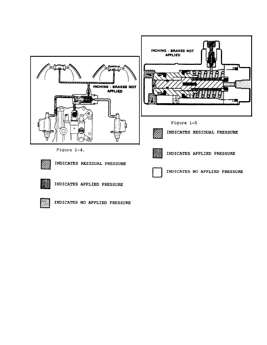
This detail of selector valve shows
action of lockout piston and inching
piston during inching operations.
(Refer to Fig. 1-5).
When the left foot inching pedal is applied,
the primary lockout piston is forced in and
blocks the inlet passage from the right
master cylinder. Then the pressure rises,
and the inching piston moves to start dis-
engaging. the transmission without brake
application. (Refer to Fig. 1-4)
1-7
|
|
Privacy Statement - Press Release - Copyright Information. - Contact Us |
