 |
|||
|
|
|||
|
Page Title:
SERVICE BRAKE AND INCHING CONTROL SYSTEM |
|
||
| ||||||||||
|
|
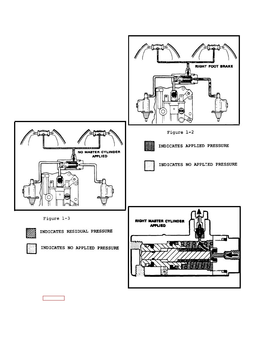 SERVICE BRAKE AND INCHING
1-28.
CONTROL SYSTEM.
Examing the inching and brake circuits
you will note that we have two master
cylinders - the left one for left foot
inching and braking, the right one for
With neither
right foot braking only.
pedal applied, the inching valve is in
Note that there
a neutral position.
is no residual pressure from either
the right or left master cylinder to
the inching-and-brake selector valve
and wheel cylinders does have residual
pressure.
(Refer to Fig. 1-3)
The inching-and-brake selector valve,
mounted on top of the differential
housing, c o n t r o l s f l o w o f f l u i d t o t h e
wheel cylinders.
When the right master cylinder is applied
for braking, fluid under pressure flows
from the master cylinder, through the
s e l e c t o r v a l v e , and through the residual
check valve to both wheel cylinders.
(Refer to Fig. 1-2)
1-6
|
|
Privacy Statement - Press Release - Copyright Information. - Contact Us |
