 |
|||
|
|
|||
|
Page Title:
Figure 33. Drag Link Adjustment |
|
||
| ||||||||||
|
|
 TM 10-3930-644-14&P
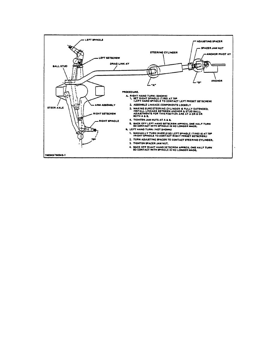
Figure 33. Drag Link Adjustment
truck, raise truck, remove blocks, and lower
3. If cylinder rod is out of adjustment loosen jam
truck to floor.
nuts (Fig 33) and turn rod in or out of anchor
pivot until properly adjusted. Tighten jam nuts to
H. DRAG LINK ADJUSTMENT
150-170 lb-ft.
1. Make certain pivot arm stop screws have been
4. Turn steering wheels to full left hand turn.
properly adjusted (Refer to TOPIC 2. paragraph
Spacer (Fig 33) should strike cylinder tube and
G, PIVOT ARM STOP ADJUSTMENT).
pivot arm screw hit stop simultaneously.
2. Turn steering wheels to full right hand turn.
5. To adjust, loosen jam nuts and turn spacer in or
Power steering cylinder rod should be fully
out until properly adjusted. Tighten jam nuts to
extended and pivot arm screw should hit stop
150-170 lb-ft.
simultaneously.
3-174
|
|
Privacy Statement - Press Release - Copyright Information. - Contact Us |
