 |
|||
|
|
|||
|
|
|||
| ||||||||||
|
|
 TM 10-3930-644-14&P
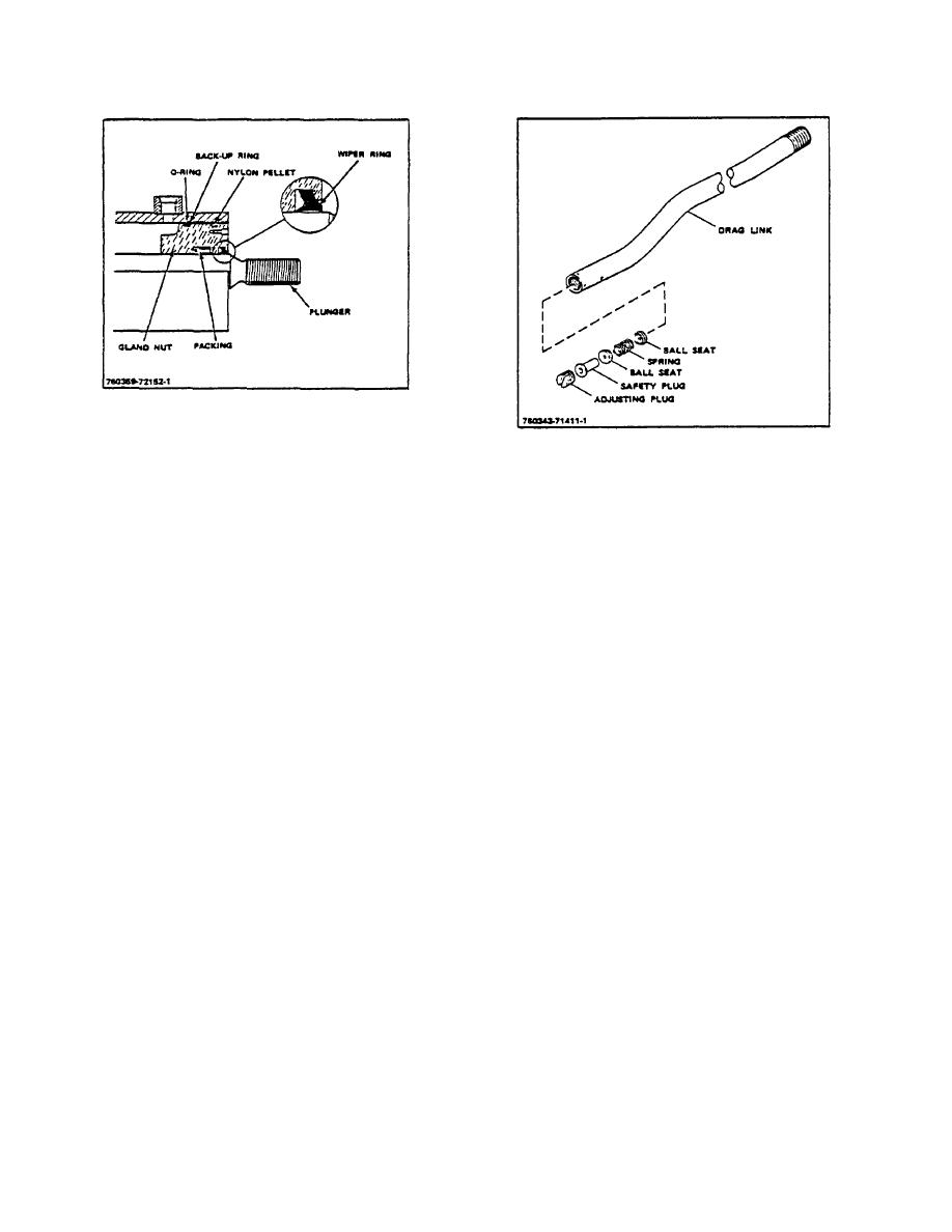
Figure 31. Cylinder Assembly
b. Usually no adjustment is required upon
Figure 32. Drag Link Components
installation; make certain that O-rings are
not twisted.
E. DRAG LINK DISASSEMBLY
c. Check to see that the ring is of correct
1. Remove adjusting plug, safety plug, ball seats
size to give a "squeeze" in the installed
and spring from drag link tube (Fig 32).
position.
2. Clean all parts in a suitable solvent. Be certain
11. Do everything possible to keep all hydraulic
all dirt and contaminants are removed.
parts as clean as possible. Keep dirt and fine
metal particles from packing and plungers.
3. Inspect all parts for cracks, nicks or other
Such material can quickly damage packing and
damage. Replace any parts that are worn or
score plungers.
damaged.
12. Inspect bushing and lube fitting in anchor pivot
F. DRAG LINK REASSEMBLY
assembly. Replace any damaged or worn parts.
Install one ball seat then the spring and the second ball
D. CYLINDER REASSEMBLY
seat followed by the safety plum and adjusting plug in
the end of the drag link tube.
Reverse disassembly procedure when installing new
parts.
G. INSTALLATION
1. Install new packing and bearing on piston.
1. Place steering cylinder into position on truck and
secure to mounting anchor with anchor pin,
2. Install spacers on plunger rod. Be sure that
washer, and cotter pin. Cylinder should pivot
outer spacer has an O-ring in groove.
freely in anchor.
3. Install piston and plunger assembly in cylinder
2. First make certain locknut is on drag link and
tube.
connect drag link to steering cylinder by
screwing drag link into cylinder tube.
4. Install new nylon pellets, O-ring, back-up ring,
packing and wiper on paking gland nut.
3. Connect drag link to pivot arm, screw in
adjusting plug, and secure with cotter pin.
5. Install packing gland nut on plunger assembly
and cylinder tube. Gland nut must be flush with
4. Remove plugs and connect hoses to power
outer edge of cylinder tube.
steering cylinder.
6. Install adjusting spacer, jam nuts, and anchor
5. Make sure hoist is securely attached to
pivot assembly on plunger rod.
3-173
|
|
Privacy Statement - Press Release - Copyright Information. - Contact Us |
