 |
|||
|
|
|||
|
Page Title:
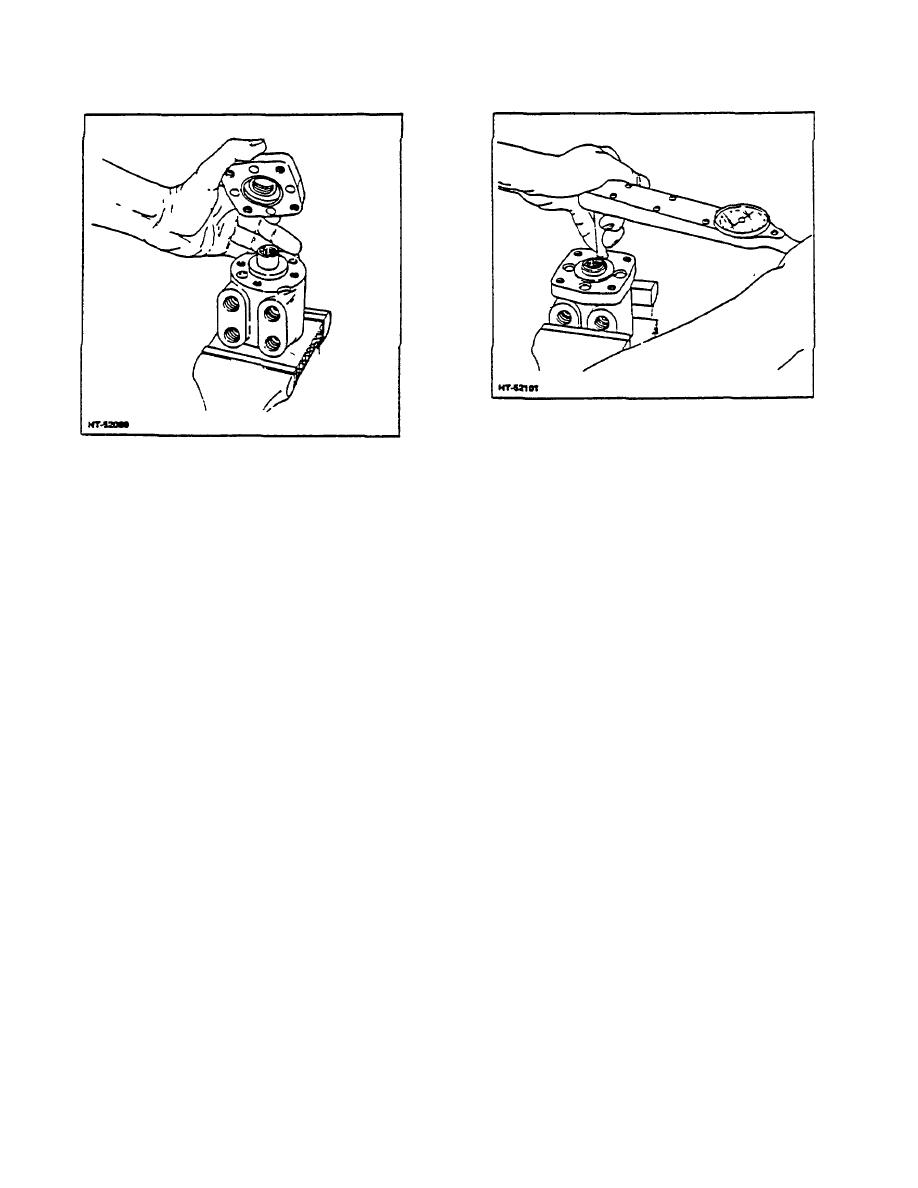
Figure 25. Installing Mounting Plate |
|
||
| ||||||||||
|
|
 TM 10-3930-644-14&P
Figure 26. Tightening Mounting Plate Capscrews
Install the meter gear star into the meter gear
Figure 25. Installing Mounting Plate
ring and slowly position the parts so the drive
does not become disengaged from the meter
15. Align the bolt holes in the cover with the tapped
gear star. Hold the plate and meter gear ring in
position on the assembly while the star is being
holes in the housing. Be sure the mounting
installed.
Rotate the meter gear slightly to
plate rests fairly flush against end of housing
engage the cross slot of the drive with the cross
assembly so that the cap locator bushing is not
pin and the splined end of the drive will drop
cocked. Install the 4 mounting plate capscrews
down against the plate.
and torque gradually and evenly to a setting of
250 lb-in. (Fig. 26).
CAUTION
Alignment of the cross slot in the
16. Reposition housing in vise and clamp across the
drive with the valleys between the
edges of the mounting plate. Be sure the spool
teeth of the meter sear star
and sleeve are flush or slightly below the 14-
determines the proper valve timing of
the unit. There are 12 teeth on the
hole surface of the housing.
spline and 6 on the star. Alignment
will be right in 6 positions and wrong
17. Wipe the upper surface of the housing clean
in 6 positions. Should the parts slip
with the palm of your hand or with your thumb.
out of position during this part of the
Clean each part of the flat surfaces in a similar
reassembly, make certain that proper
way as it is ready for assembly.
alignment is obtained.
18. Install the plate over this assembly so the bolt
22. Place the spacer in position at the end of the
holes in the plate are aligned with the tapped
meter gear star. If spacer does not fit flush with
holes in the housing.
the gear surface, the drive has not properly
engaged the cross pin. After drive is correctly
installed, place the meter end cap over the
19. Place the meter gear ring on the assembly so
assembly. Install 2 capscrews, finger tight, to
the bolt holes are aligned.
maintain alignment of the parts.
20. Install the splined end of the drive into the meter
23. Install all 7 capscrews and torque them
gear star so the slot at the control end of the
gradually and evenly to 150 lb-in (Fig. 28).
drive is aligned with the valleys between the
meter gear teeth (Fig. 27).
24. To install the steering column, rotate the shaft to
engage the splines while bringing the surfaces
21. Push splined end of drive through the gear until
into contact.
spline extends about one half its length beyond
25. Install the capscrews and torque to 280 lb-in.
meter gear star. Hold it in this position while
installing it in the unit. Note position or direction
of cross pin within the unit.
3-169
|
|
Privacy Statement - Press Release - Copyright Information. - Contact Us |
