 |
|||
|
|
|||
|
|
|||
| ||||||||||
|
|
 TM 10-3930-644-14&P
7. Attach a lifting chain and hoist to transmission.
Remove transmission mount hardware and lift
transmission from truck.
CAUTION
Ensure that all attachments to
transmission assembly that could
hinder
removal,
have
been
disconnected and secured out of the
way.
D. DISASSEMBLY
After transmission is removed from truck, place on a
suitable work area, and proceed as follows for complete
disassembly:
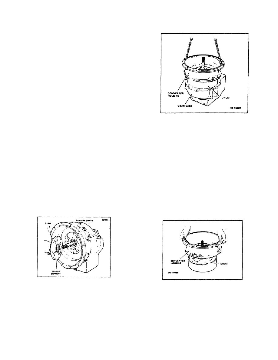
Figure 1-5. Removing Housing and Drum
1. Carefully clean exterior of transmission
to
a chain to the housing and remove housing and
prevent contamination of system.
drum assembly as a, unit, taking care not to
damage the seal rings in collector ring on gear
2. Disconnect tube
from
control
valve
and
case.
convertor housing.
6. To remove the converter housing from the drum,
3. Remove capscrews from valve block, and
remove the snap ring on the turbine shaft and
remove from transmission. Cover opening to
slide housing from drum assembly. Bearing will
avoid contamination. See Figure 1-3.
remain in housing. (Figure 1-6.)
4. Slide converter off turbine shaft. Then mark the
7. Remove for ward gear and shaft:
pump and the housing to ensure the proper
reinstallation, and remove capscrews holding
a. Remove capscrews and lockwashers
the pump and collector ring to converter
holding cap to housing and remove cap.
housing. It may be necessary to tap the pump
assembly with a rawhide hammer to free it from
b. Remove inner snap ring from the splined
the gasket. (See Figure 1-4.)
section of the forward
Figure 1-4. Pump Removal
Figure 1-6. Removing Clutch Drum from
Converter Housing.
5. Lay the transmission on the gear case side as
shown in Figure 1-5. Remove capscrews which
mount the converter housing to the gear case.
Then, attach
R-171-1
3-119
|
|
Privacy Statement - Press Release - Copyright Information. - Contact Us |
