 |
|||
|
|
|||
|
|
|||
| ||||||||||
|
|
 TM 10-3930-644-14 & P
6. Brush Holder and Regulator Replacement.
CAUTION
Do not use high voltage to check
After removing the three attaching nuts, the
these units, such as a 110 volt test
stator, and diode trio screw (Figs. 2-9 and 2-10),
lamp.
the brush holder and regulator may be replaced
To replace the rectifier bridge, remove the
by removing the two remaining screws. Note
attaching screws, and disconnect the capacitor
the two insulators located over the top of brush
lead. Note the insulator between the insulated
clips in Figure 2-6; these two screws have
heat sink and end frame (Fig. 2-9). Rectifier
special insulating sleeves over the screw body
bridges may vary in appearance but are
above the threads. The third mounting screw
completely interchangeable in these generators.
may or may not have an insulating sleeve. If
not, this screw must not be interchanged with
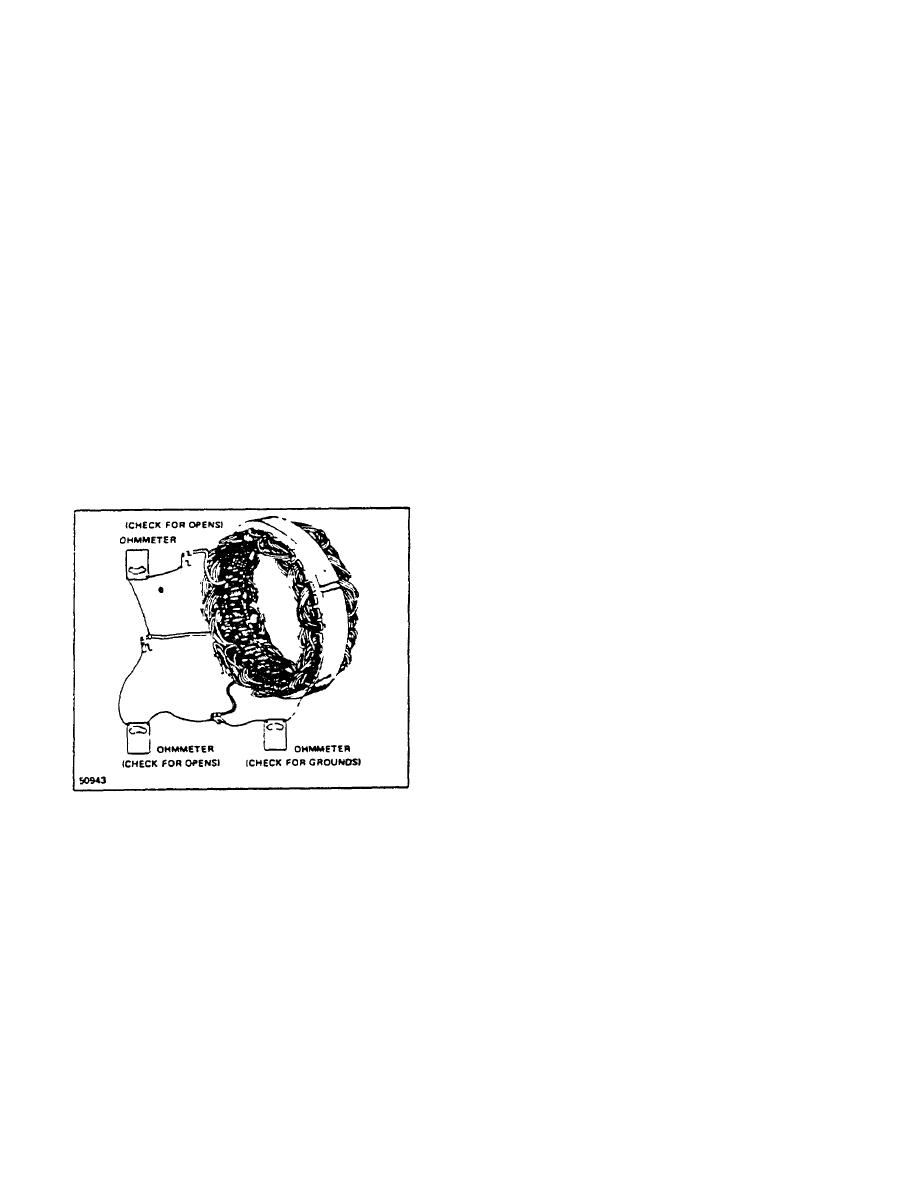
5. Stator Checks
either one of the other two screws, as a ground
may result, causing no output or uncontrolled
The stator windings may be checked with a 110
generator output.
Regulators may vary in
volt test lamp, or with an ohmmeter. If the lamp
appearance but are completely interchangeable.
lights, or if the meter reading is low when
connected from any stator lead to the frame, the
7. Slip Ring Servicing
windings are grounded. If the lamp fails to light,
or if the meter reading is high when successively
If the slip rings are dirty, they may be cleaned
connected between each pair of stator leads, the
and finished with 400 grain or finer polishing
windings are open (Fig. 2-11).
cloth. Spin the rotor, and hold the polishing
cloth against the slip rings until they are clean.
CAUTION
The rotor must be rotated in order to
clean the slip rings evenly.
Cleaning the slip rings by hand
without spinning the rotor may result
in flat spots on the slip rings, causing
brush noise.
Slip rings which are rough or out of round should
be trued in a lathe to .002" maximum indicator
reading. Remove only enough material to make
the rings smooth and round. Finish with 400
grain or finer polishing cloth and blow away all
dust.
8. Bearing Replacement and Lubrication
Figure 2-11. Checking Stator Windings
The bearing in the drive end frame can be
removed by detaching the retainer plate screws,
A short circuit in the stator windings is difficult to
and then pressing the bearing from the end
locate without laboratory test equipment due to
frame. If the bearing is in satisfactory condition,
the low resistance of the windings. However, if
it may be reused, and it should be filled one-
all other electrical checks are normal and the
quarter full with Delco-Remy lubricant No.
alternator fails to supply rated output, shorted
1948791 before reassembly.
stator windings Are indicated
CAUTION
Do not overfill bearing as this may
cause it to overheat.
Use only
1948791 lubricant.
R-146-1
3-88
|
|
Privacy Statement - Press Release - Copyright Information. - Contact Us |
