 |
|||
|
|
|||
|
|
|||
| ||||||||||
|
|
 TM 10-3930-644-14&P
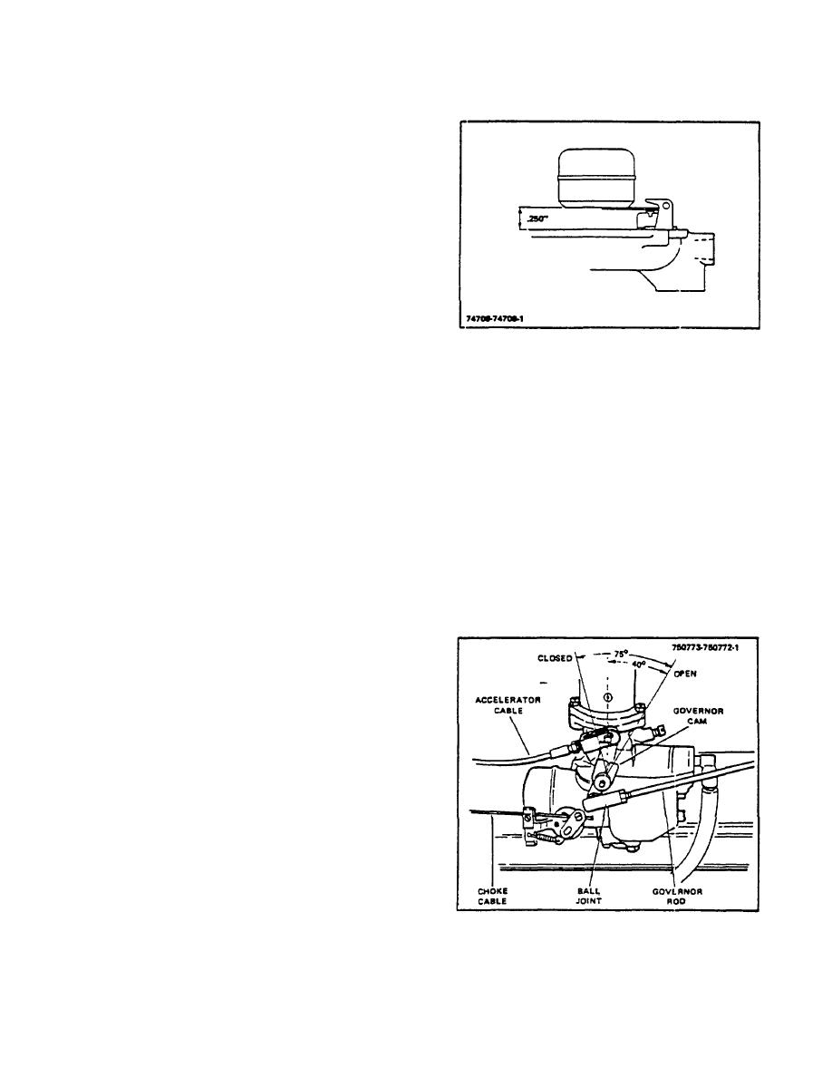
7. Install float and lever assembly on throttle body
and insert axle shaft through float lever.
8. Measure distance from gasket on throttle body.
Distance (Fig. 4-7) should be .250" from gasket
face to nearest edge of float. Use a long nosed
pliers to bend lever as necessary to attain this
measurement.
NOTE
Do not. bend, twist or apply pressure
to float bodies.
The float bodies
when viewed from the free end of the
bodies, must be centered and at right
angles to the machined gasket
surface and must move freely on the
float axle shaft.
Figure 4-7. Float Setting
9. Install choke shaft p cking in recess in choke
a
bracket and tap bracket in place on fuel bowl
4. Install yoke on end of accelerator cable
throat to seat packing. Secure bracket with
(Fig. 4-8) over carburetor lever and install yoke
screws.
pin through yoke and lever. secure yoke to lever
with cotter pin.
10. Install choke shaft and lever assembly and
return spring.
5. Install choke cable ( ig. 4-8) through clamp-on
F
choke bracket and into block. Tighten screw to
11. Insert choke valve on lever and center valve in
secure cable in block. Tighten clamp screw.
casting before tightening screws.
6. Refer to TOPIC 6 to adjust carburetor and choke
12. Install main nozzle through bottom of casting.
linkage.
Place new O-ring and gasket in recess and
install power jet in fuel bowl behind nozzle.
7. If the carburetor levers (Fig. 4-8) were removed
Install nozzle plug.
during disassembly, adjust governor lever on
13. Invert throttle body and lower fuel bowl over
shaft to angle illustrated.
floats. Be sure venturi guides float bodies into
position.
14. Install bowl screws and lockwashers.
Tighten
screws gradually until all are tight.
15. Install drain plug in bottom of bowl.
G. INSTALLATION
1. If studs were removed, install studs in threaded
holes in carburetor flange. Use a new gasket
and install carburetor on manifold.
Secure
carburetor with nuts and lockwashers.
2. Connect inlet fuel line to carburetor. Install air
cleaner hose on carburetor and tighten hose
clamps.
3. Connect governor rod to carburetor lever. Insert
threaded end of ball joint (Fig. 4-8) through lever
and secure with ball joint nuts.
Figure 4-8. Carburetor Linkage Adjustments
R-123-1
3-64
|
|
Privacy Statement - Press Release - Copyright Information. - Contact Us |
