 |
|||
|
|
|||
|
Page Title:
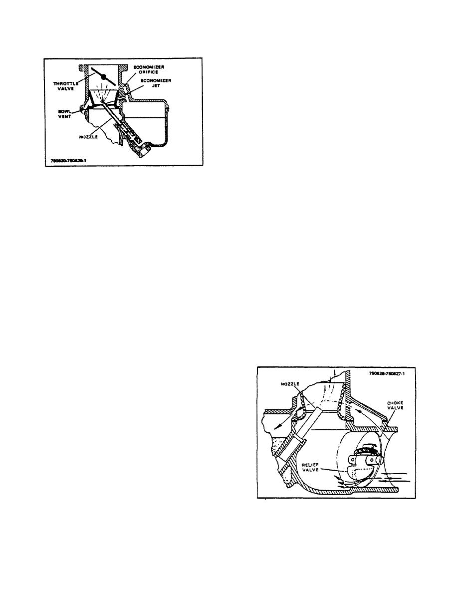
Figure 4-4. Back Suction System |
|
||
| ||||||||||
|
|
 TM 10-3930-644-14&P
As this vacuum decreases as the throttle
approaches wide open position, less air is drawn
out of the fuel bowl chamber and additional fuel
flows to the engine to provide the extra richness
required for operation at heavy loads where
maximum horsepower is necessary.
5. Choke System.
The choke system is used during cold starting
and the warm-up period. Under these cold
conditions it is necessary to supply an extra rich
mixture of fuel and air, as only the "light ends" or
more volatile portions of the fuel will vaporize
with the manifold and air temperatures at the
Figure 4-4. Back Suction System
cold temperatures. Consequently it is necessary
that a large quantity of fuel be available so that
the fuel flow through the carburetor can be
there will be enough "light ends," to combine
controlled to provide the proper mixture
with the air to form a combustible mixture for
proportions for the engine.
starting the engine.
All the air that enters the fuel bowl chamber (Fig.
The function of the choke valve (Fig. 4-5) is to
4-4) must first pass through the air cleaner and
restrict the amount of air that can enter the
the bowl vent. The size of the bowl vent controls
carburetor and to increase the vacuum on the
or limits the amount of air that can enter the fuel
nozzle so that additional fuel will be drawn into
bowl chamber. The amount of air that is drawn
the manifold. As soon as the engine fires and
out of the fuel bowl chamber is controlled by the
runs the rich mixture must be rapidly reduced to
size of the economizer jet, the economizer
prevent stalling. This change in mixture should
orifice and the position of the throttle valve as its
be accomplished by the operator repositioning
position determines the manifold vacuum or
the choke valve. To help reduce the sensitivity
suction on the economizer orifice.
As the
of the choke valve position, use is made of a
throttle valve is opened from the fast idle
spring loaded relief valve. This valve opens
position the economizer orifice is gradually
automatically with engine speed and load and
exposed to manifold suction, and air flows from
eliminates a great deal of manipulation of the
the fuel bowl chamber, through the economizer
choke on the part of the operator.
jet and out the economizer orifice. This air must
be replaced by air entering through the bowl
vent but as the size of the bowl vent restricts the
amount of air that can enter, the resultant.
Pressure in the fuel bowl chamber will be
lowered, reducing the difference in air pressure
between the nozzle and the fuel bowl chamber.
The flow of fuel will therefore be retarded so that
the exact economy mixture ratio will be delivered
to the engine at this particular throttle opening.
Opening the throttle valve further exposes the
entire economizer orifice to manifold suction,
resulting in additional air being removed from
the fuel bowl chamber, again leaning out the
mixture ratio to the correct proportions for this
new throttle position.
After the economizer
orifice is fully exposed to manifold vacuum, the
amount of air that is drawn out of the fuel bowl
chamber is controlled by the manifold vacuum or
Figure 4-5. Choke System
(or suction) at any given throttle valve position.
3-61
|
|
Privacy Statement - Press Release - Copyright Information. - Contact Us |
