 |
|||
|
|
|||
|
|
|||
| ||||||||||
|
|
 TM 10-3930-644-14&P
The rear face of the crankcase provides an accurately
3. Clean pistons of all carbon, being particularly
machined surface for mounting the flywheel housing. A
careful to see that the ring grooves are clean
semi-circular groove in the rear face of the crankcase
and oil drain holes in oil ring groove are clean of
around the rear main bearing receives a semi-circular oil
all carbon. Inspect pistons for any cracks in
guard, and a filler block which is held in place by two
head or in piston pin bosses.
machine screws. Oil guard and filler block contain a
4. Clean oil passage in each connecting rod and
pressed-in oil seal to prevent the entrance of foreign
check each piston and rod assembly for correct
material around the main bearing.
alignment.
The camshaft extends the length of the left side of the
5. Clean valve guides and valves to remove head
crankcase and runs in three pressed-in bushings which
and stem deposits. Check fit of valves in guides
are drilled for pressure lubrication from drilled passages
and tension of valve springs.
in the crankcase.
6. Check that valve tappets are free fit in block
without perceptible side play or shake. Inspect
The three main bearing locations are machined to
for rough or grooved faces, and be sure heads
receive thin-wall precision type bearings. No shims are
of adjusting screws are smooth.
used between the case and the bearing cap. The center
main bearing is flanged on both sides to absorb
7. Check general condition of camshaft. Journals
crankshaft end thrust and to locate the crankshaft
should not be scored or burred. Cams should
lengthwise. The three main bearing caps are doweled
be smooth and free from burrs or grooving.
on both sides to provide for an accurate and rigid
8. Inspect crankcase for cracks, especially in the
alignment. The upper and lower halves of the precision
exhaust valve area.
type bearing shells are alike and are located by small
tabs with fit recesses in the case. The front and center
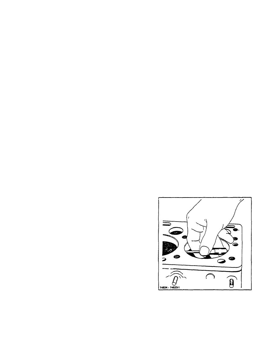
9. Clean the ring of carbon from around the top of
bearings have a single groove in each shell which
the cylinder bore formed above the travel of the
extends out a short distance from the oil hole and blends
top ring.
into the bearing contour. The rear bearing has two holes
10. Determine the original diameter of the cylinder
connected by an oil channel.
barrel by checking this unworn area with an inside
If the same connecting rod bearings are to be re-used,
micrometer at intervals of approximately 45.
be sure the bearing shells are kept in order with respect
to which connecting rod they go in, which is top and
which is bottom. However, re-use of bearing shells is
not recommended.
B. REMOVAL
Refer to ENGINE REMOVAL AND INSTALLATION.
Refer to relevant sections for removal/ installation
instructions.
C. INSPECTION
Important points on cleaning and inspection to be
observed are as follows:
1. Clean oil pan thoroughly. Remove oil gallery
plug and clean all passages with solvent and
compressed air.
Clean valve compartment
thoroughly. Clean crankshaft oil passages.
2. Carefully inspect the condition of the crankshaft
Figure 11-2. Measuring Original Bore Diameter Above
journals and crank pins. These surfaces must not
Ring Travel.
be scored or burred and should be checked with
a micrometer against specifications as tabulated
in TOPIC 1. FITS AND TOLERANCES
R-104-1
3-40
|
|
Privacy Statement - Press Release - Copyright Information. - Contact Us |
