 |
|||
|
|
|||
|
Page Title:
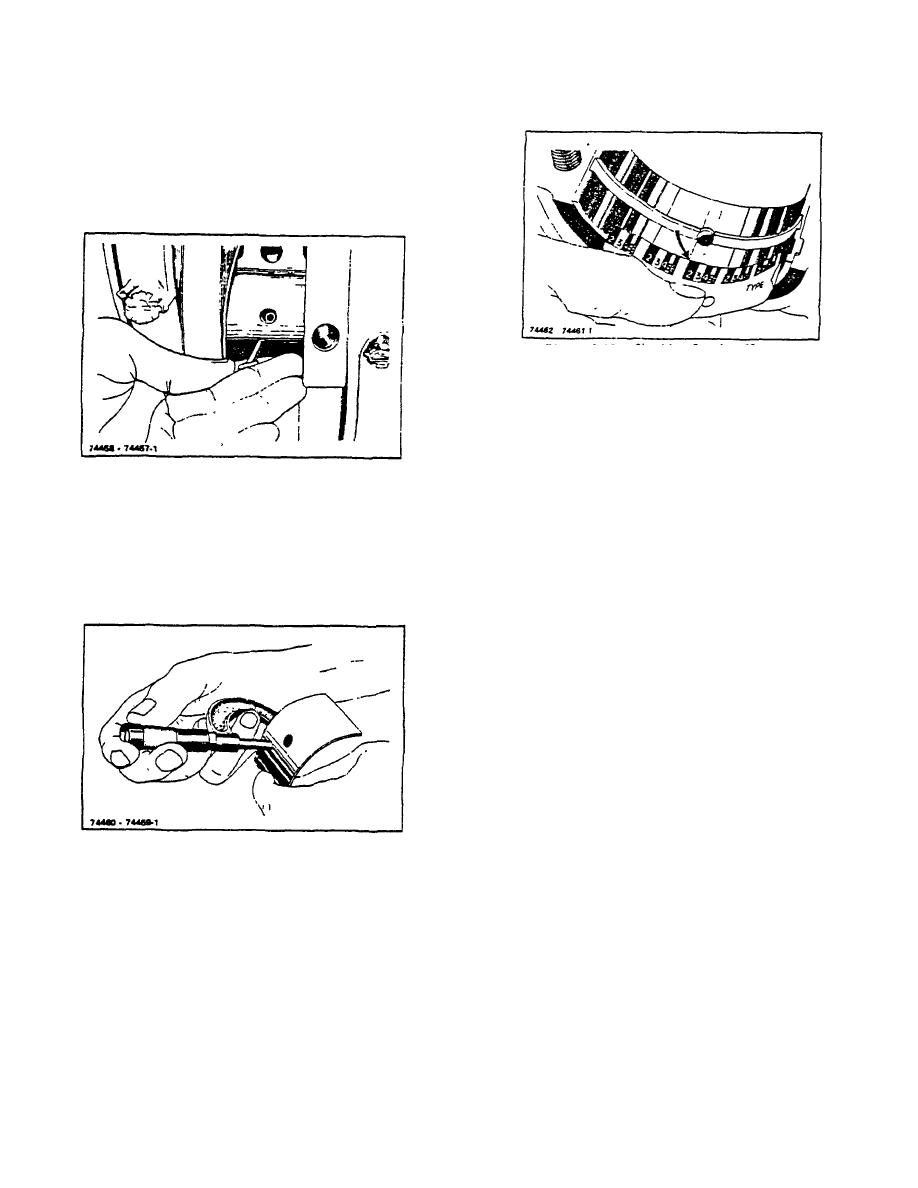
Figure 6-8. Removing Upper Half of Main Bearing Shell |
|
||
| ||||||||||
|
|
 TM 10-3930-644-14&P
most parts houses, which is a pin with an angular
head (Figure 6-8). This tool may be inserted in the oil
hole of the crankshaft and, as the crankshaft is turned
in a clockwise direction, the head of the pin picks up
the bearing shell and forces it out of the bore in the
block.
Figure 5-10. Checking Bearing Clearance with
Plastigauge
CAUTION
When using this method 00 NOT
TURN the crankshaft, as that would
destroy the Plastigauge.
Figure 6-8. Removing Upper Half of Main Bearing Shell
By placing the Plastigauge in the bearing and
The thickness of the bearing shells is given in TOPIC
tightening it in place, the width of the Plastigauge
1. FITS AND TOLERANCES. If this thickness has
after crushing determines the bearing clearance, as
been reduced more than .0005" beyond the
shown in Figure 6-10.
maximum allowable tolerance the bearing shell must
be replaced (Figure 6-8).
The term "crush" is generally understood as the
projection of the bearing edges above flush with the
mating surfaces of the nearing seat and cap. This
crushing action forces the bearing halves into close
contact with their seats for greater rigidity and good
heat conduction.
The correct amount of crush has been allowed during
the manufacture of the bearings, and so attention to
that detail is necessary at the time of replacement.
The use of a torque wrench for tightening bearings is
necessary to insure sufficient "crush" on the bearings,
to force the shells against the crankcase metal
without distortion.
An alternative method (Figure 6-11) is to use a piece
Figure 6-9. Measuring Bearing Thickness
of 1/2" feeler stock lengthwise in the bearing shell, on
a film of oil. The thickness of the feeler stock should
If visual inspection of the crankshaft has shown no
be equivalent to the maximum clearance permissible
indication of excessive wear or scoring, the clearance
in the bearing.
of the bearings should be checked with feeler stock.
Assemble the bearing cap and tighten the screws,
Check each bearing, one at a time, by using a piece
torquing them to specification, then try to turn the
of Plastigauge of a diameter specified to check
crankshaft by hand to determine whether or not a
certain clearances.
drag is felt.
If a definite drag is felt and the piece of feeler stock is
equivalent to, but
R-104-1
3-19
|
|
Privacy Statement - Press Release - Copyright Information. - Contact Us |
