 |
|||
|
|
|||
|
Page Title:
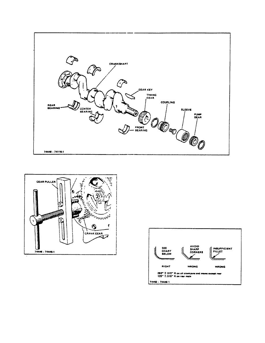
Figure 6-2. Crankshaft Assembly |
|
||
| ||||||||||
|
|
 TM 10-3930-644-14&P
Figure 6-2. Crankshaft Assembly
Insert oil-soaked paper strips in the 'Y' blocks to avoid
marring the shaft. The dial indicator reading should be
taken at the center main bearing journal.
The run-out, or total variation in the indicator reading
during one complete revolution of the crankshaft, is
limited to .002". Straighten crankshaft, if necessary, to
be within .002" reading.
Check the connecting rod and main bearing
Figure 6-3. Removing Crank Gear (Typical)
C. CRANKSHAFT INSPECTION AND SERVICING
Check for run-out by mounting the crankshaft in 'V'
blocks at the front and rear main bearing Journals.
Figure 6-4. Crankshaft Fillet Radii
R-104-1
3-17
|
|
Privacy Statement - Press Release - Copyright Information. - Contact Us |
