 |
|||
|
|
|||
|
|
|||
| ||||||||||
|
|
 TM 10-3930-644-14&P
TOPIC 5. CYLINDER HEAD
A. DESCRIPTION
The cylinder head is an alloy cast iron unit, secured to
the engine block with special hardened studs and
capscrews. The head seals the top end of the cylinders
to form the combustion chambers and passages for the
intake of the air-fuel mixture, and the expulsion of
exhaust gases, as well as cored passages through
which the coolant flows to prevent overheating.
B. REMOVAL
1. Drain water from block by opening water drain
cock.
2. Drain radiator.
3. Loosen clamps on upper radiator hose and
remove hose, taking care not to damage
Figure 5-1. Cleaning Carbon from Combustion Chamber
thermostat located at cylinder head end of hose.
4. Disconnect water bypass tube from water pump.
3. Make sure that gasket contact surfaces on the
5. Disconnect wire from water temperature sender.
head are clean, smooth and flat.
6. Disconnect spark plug ignition cables from spark
4. Inspect cylinder head for cracks, holes and
plugs, and identify each cable.
warpage. Replace damaged heads.
7. Remove spark plugs, and cap or tape exposed
ports.
8. Remove capscrew or nut holding distributor
clamp to cylinder head. Remove distributor 9.
Refer to TOPIC 3 and remove the manifold.
10. Remove cylinder head mounting capscrews and
stud nuts.
11. Lift the cylinder head and gasket off the engine
and place it on a work bench.
12. With a clean, dry cloth wipe all exposed engine
internal areas free of water and place a
protective cover, such as a plastic sheet, over
exposed cylinders.
C. SERVICING
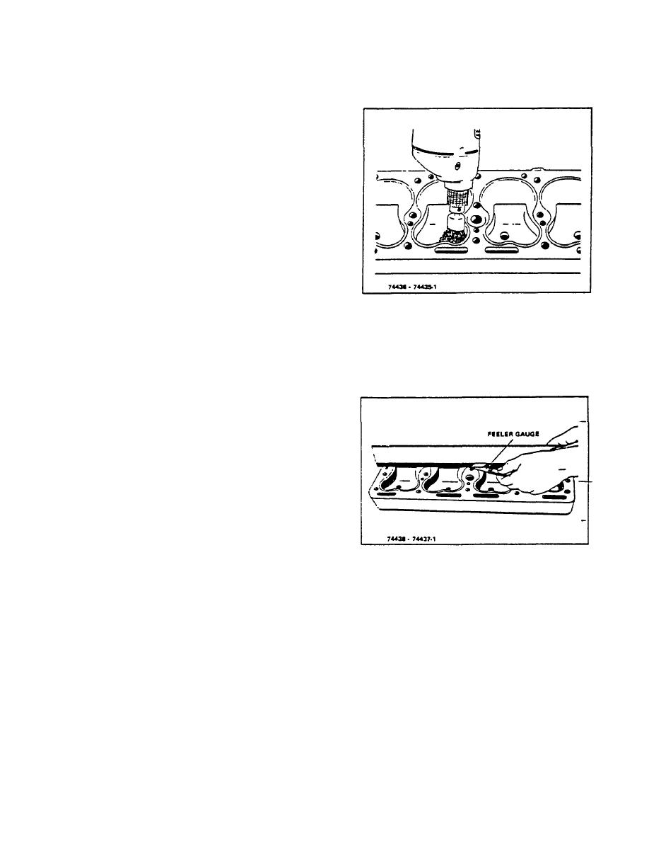
Figure 5-2. Checking Cylinder Head Flatness
1. Using a scraper and wire brush, remove all
Lengthwise
carbon from combustion areas. See Figure 5-1.
2. Clean the cylinder head thoroughly Figure 5-1.
5. Check out-of-flatness with straight edge and
Cleaning Carbon from Combustion Chamber
feeler gauge: maximum permissible is .00075"
with an acceptable cleaning solvent and dry
per inch of width or length (Figures 5-2 and 5-3).
thoroughly with compressed air.
Thus, for a cylinder head 16" long, maximum
permissible lengthwise out-of-flatness is .012".
Out-of-flatness should vary gradually and
uniformly from end to end and side to side.
Localized depressions or high spots should not
exceed .003".
R-104-1
3-13
|
|
Privacy Statement - Press Release - Copyright Information. - Contact Us |
