 |
|||
|
|
|||
|
Page Title:
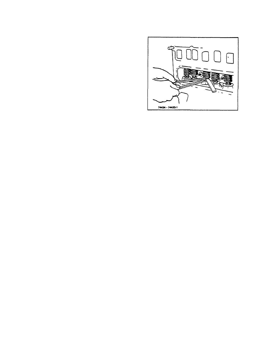
Figure 4-16. Adjusting Valve Tappet Clearance |
|
||
| ||||||||||
|
|
 TM 10-3930-644-14&P
2. Remove valve tappet cover from left side of
engine.
This includes disconnecting and
removing fuel pump with front cover.
3. Remove the spark plug from No. 1 cylinder.
4. Place thumb over the spark plug opening and
slowly crank the engine until an outward
pressure can be felt. Pressure indicates No. 1
piston is moving toward top dead center of the
compression stroke. Continue cranking until the
timing mark on the flywheel is in center of
opening in flywheel housing. Both valves are
then closed on the compression stroke of No. 1
cylinder.
5. Use two thin open end wrenches when making
adjustment. The lower wrench is used to raise
Figure 4-16. Adjusting Valve Tappet Clearance
or lower the tappet adjusting screw after the
locknut has been loosened. Never attempt to
valves in succession, according to the firing
adjust without first loosening the adjusting screw
order of the engine: 1-3-4-2.
locknut. The feeler gauge should pass between
the valve stem and tappet adjusting screw with a
7. Replace the valve tappet cover and other
slight drag when the valve lash is properly
removed parts. Make sure cover makes an oil-
adjusted.
tight seal with the crankcase. Replace gasket.
6. Crank the engine one-half revolution at a time,
8. Replace the spark plug and coil wire.
and check the clearance of each valve; adjust if
necessary. Do this on each set of cylinder
R-104-1
3-12
|
|
Privacy Statement - Press Release - Copyright Information. - Contact Us |
