 |
|||
|
|
|||
|
Page Title:
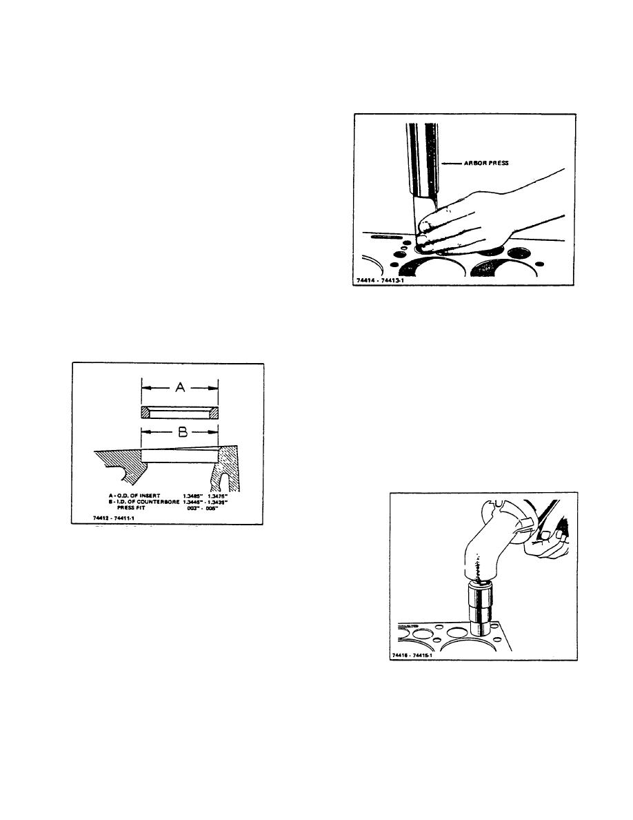
Figure 4-5. Insert and Counterbore Dimensions |
|
||
| ||||||||||
|
|
 TM 10-3930-644-14&P
Inspect all exhaust valve inserts in the block and
assures that the insert is seated firmly on the
replace any that are loose, cracked or otherwise
bottom of the counterbore.
damaged. Use puller for removing faulty insert
as shown in Figure 4-4.
When required to replace with new insert, clean
and counterbore for .010" larger insert using
counterbore tool with correct fitting pilot.
When machining the counterbore, be sure to go
deep enough with the tool to clean up the
bottom; so that, the insert will have full contact to
carry away the heat.
It is not recommended to install new inserts
having the same outside diameter as the one
removed. Refer to Dimensions of Standard
Inserts and Counterbores shown in Figure 4-5.
A - O.D. of Insert ................ 1.3485"-1.3475"
Figure 4-6. Installing Valve Seat Insert with an Arbor
B - I.D. of
Press
Counterbore .................. 1.3445"-1.3435"
Press Fit .............................. .003"-.005"
3. Valve Seat Grinding
Grind the Intake and exhaust valve seats in the
block (Figure 4-7) in accordance with specified
dimensions in TOPIC 1.
FITS AND
TOLERANCES. Before removing the arbor,
indicate the seat. Total Indicator reading of the
run-out must not be more than .002". Use a pilot
having a solid stem with a long taper, as all
valve seats must be ground concentric and
square with either new or worn valve stem guide
holes (Figure 4-8).
Figure 4-5. Insert and Counterbore Dimensions
When OVERSIZE inserts are used, dimensions
of the insert and counterbore increase
proportionately .010" to .020" depending on the
oversize.
New insert installation should have a press fit.
Chill Insert in container with dry ice for 20
minutes before assembling.
Insert may then be installed in the counterbore
Figure 4-7. Grinding Valve Seat
using a piloted driver, tapping in place with very
light hammer blows, without the possibility of
shearing the side walls (Figure 4-6).
This
R-104-1
3-9
|
|
Privacy Statement - Press Release - Copyright Information. - Contact Us |
