 |
|||
|
|
|||
|
Page Title:
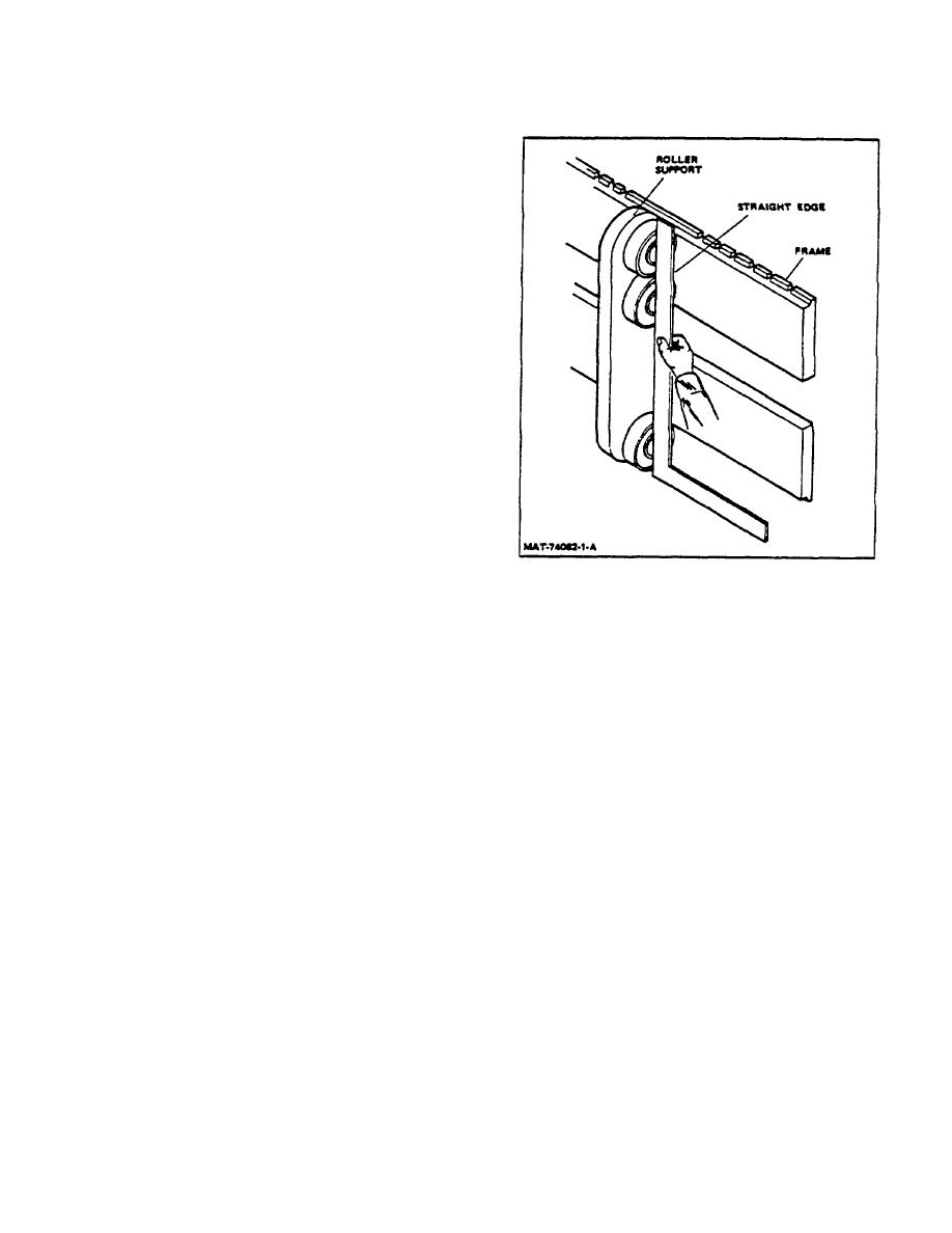
Figure 3. Checking Bearing Alignment |
|
||
| ||||||||||
|
|
 TM 10-3930-644-14&P
1. Place two pieces of wood, approximately 2"
thick, underneath forks (or attachments), (one
towards front of the forks and one underneath
carriage frame.
2. Remove carriage stop capscrews (or stop, if
applicable).
3. Remove lift chain anchor pins (or connecting
link, if applicable), and disconnect chains from
carriage.
4. Ensure that no attachments secure the carriage
to the mast. Start engine and raise inner mast
high enough to clear inner mast uprights.
5. Back lift truck out of the way and move carriage
to desired location.
NOTE
If carriage is of the canted bearing
design, it must be adjusted before
installation.
Refer to following
PARAGRAPH C, ADJUSTMENT.
C. ADJUSTMENT-CANTED BEARING TYPE (Figure 1)
Figure 3. Checking Bearing Alignment
1. Use an inside spanning tool and check inside of
web of inner mast assembly and determine
D.
INSTALLATION (EXTRA-LIFT AND HIGH FREE
narrowest point where bearings contact inner
LIFT 3,5000 14,000 lb AND ALL TRI-MAX)
mast uprights.
1. Raise inner mast high enough to clear carriage
2. Set outside spanning tool to match inside
assembly bearings.
spanning tool. Lock tool in position.
2. Position lift truck so that inner mast uprights are
3. Install bearings on roller studs on carriage.
directly centered over carriage bearings. Slowly
Span bearings on carriage assembly at the
lower inner mast making sure carriage bearings
maximum camber point with outside spanning
slide into inner mast uprights.
tool. Span all sets of bearings. Shim bearings
to produce maximum .015 inch clearance with
3. Reinstall carriage stop capscrews (or stop, if
spanning tool.
applicable).
4. To check bearing alignment, place a
4. Reinstall lift chain anchor pins (or connecting
straightedge against stud centerline to all
link, if applicable), and reinstall lift chains.
bearings on both sides of carriage assembly.
No visible gap should be seen between bearings
and the straightedge (Fig 3).
2-102
|
|
Privacy Statement - Press Release - Copyright Information. - Contact Us |
