 |
|||
|
|
|||
|
|
|||
| ||||||||||
|
|
 TM 10-3930-644-14&P
C. INSTALLATION
1. Attach drag link to pivot arm and to cylinder.
Attach cylinder to frame.
2. Connect hydraulic lines to cylinder.
3. Loosen suction hose at hydraulic pump to make
certain hose is not air-bound. With suction hose
loosened, air will leak out.
CAUTION
Make certain hydraulic oil is up to the
"Full" mark on dipstick.
4. Tighten hose and lower truck to floor.
Figure 7. Drag Link Components (PRT)
TOPIC 7. WHEELS AND TIRES
The steer wheels are located at the rear of the lift truck,
NOTE
at the counterweight end. To remove either or both
Refer to REPAIR MANUAL for
steer wheels, it is recommended that the drive wheels be
DISASSEMBLY and REASSEMBLY.
properly blocked and that a properly attached hoist chain
and jacks or blocks be used to raise rear of truck for
B. INSTALLATION (PNEUMATIC TYPE)
steer wheel tire removal.
1. Install tire and rim assembly on hub.
A. REMOVAL (PNEUMATIC TYPE)
2. Secure tire and rim assembly with nuts and
1. Ensure drive wheels are securely blocked and
3. Remove clocks lower truck and release
set parking brake to prevent truck from rolling.
handbrake.
2. Remove the nuts and lockwashers attaching the
rims to the bolts La the wheel hub. (See Fig
8/11)
3. Pull the tire and rim assembly from the hub.
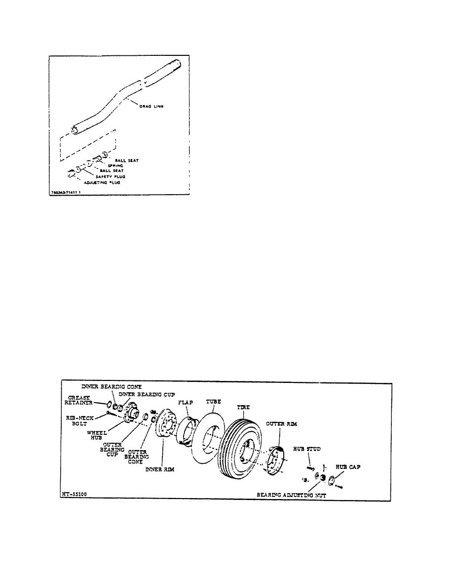
Figure 8. Steer Wheel Assembly (Pneumatic Tire Type)
2-83a
|
|
Privacy Statement - Press Release - Copyright Information. - Contact Us |
