 |
|||
|
|
|||
|
|
|||
| ||||||||||
|
|
 TM 10-3930-644-14&P
2. Tighten capscrews (5) to a torque of 14 to 16 in.
REASSEMBLY
and
DRIVE
WHEEL
lbs.
REASSEMBLY.
3. Hold capscrews (5) in position and tighten nuts
7. To test the operation of the self-adjuster, after
(6) to a torque of 29 in. Lbs.
initial installation of adjuster unit, place shifting
lever in either forward or reverse and step on
4. Check slip resistance of the slide assemblies,
brake pedal. Self-adjuster should automatically
resistance must be 250 to 300 lbs.
adjust and there should be very little play in
brake pedal.
5. After the assembly is completed, the self-
adjuster should measure 5-1/4" between hole
NOTE
centers when it is fully retracted.
If there is excessive play in brake
pedal, check pedal adjustment before
6. drive wheel brake drum assembly and drive
removing brake drum unit. Refer to
wheel;
refer
to
BRAKE
DRUM
UNIT
DRIVE
WHEEL
BRAKE
ADJUSTMENT, REPAIR MANUAL.
TOPIC 4. PARKING BRAKE
A. DESCRIPTION
The brake mechanism requires no lubrication except at
time of assembly. The brake actuating mechanism,
A dual shoe mechanical brake, mounted at the drive
such as the hand lever and linkage, should be lubricated
shaft, can be used as either a parking brake or as an
periodically.
emergency brake.
The brake shoes are actuated
through a cable by an adjustable, over-center type lever,
B. ADJUSTMENT
mounted on the left hand cowl panel. (See Figure 3. )
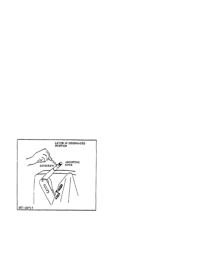
To compensate for brake lining wear, the tension on the
hand brake can be increased by adjusting the knob on
top of the hand brake lever. (See Figure 5.) The
following procedure is recommended for proper
adjustment of hand brake lever:
1. Set the hand brake lever in the fully released
position.
2. Remove the setscrew that locks the adjusting
knob in position.
3. Turn the adjusting knob-In a clockwise direction
one or two turns, then verify adjustment by
engaging the brake. Lever should pull harder to
engage brake if properly adjusted.
4. Repeat Step 3 If additional tension is required.
When satisfactorily adjusted, .turn setscrew in to
lock the adjusting knob.
Figure 5. Hand Brake Adjustment
NOTE
Refer to REPAIR MANUAL if brake
shoe adjustment is required.
2-78
|
|
Privacy Statement - Press Release - Copyright Information. - Contact Us |
