 |
|||
|
|
|||
|
Page Title:
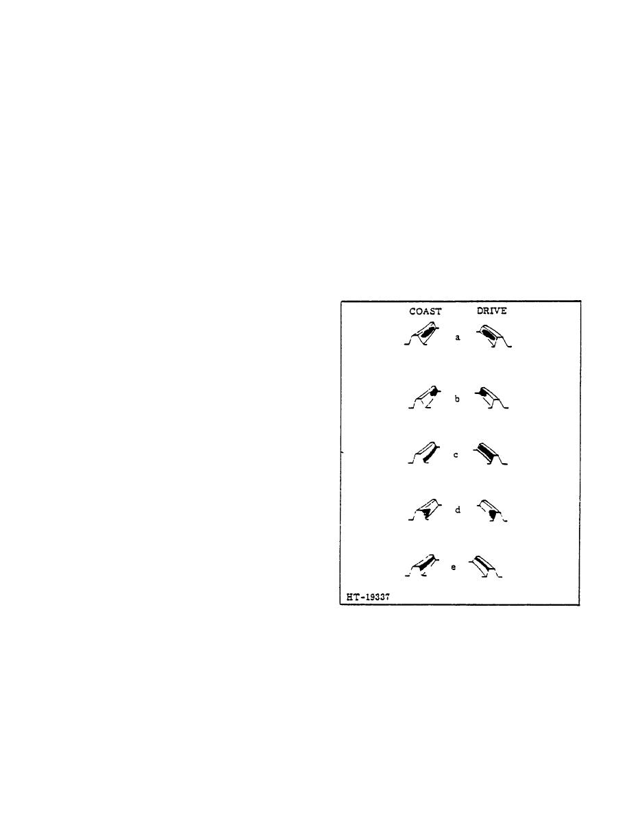
Figure 17. Differential Tooth Pattern |
|
||
| ||||||||||
|
|
 TM 10-3930-644-14&P
depth of gear tooth without breaking
4. Adjust the ring gear laterally for a backlash
contact at flank.
Move the ring gear
adjustment of .005" to .010" (backlash etched on
towards the pinion to obtain the proper
gear) by means of the differential side bearing
backlash.
adjusting nuts.
To increase the backlash,
loosen the adjusting nut nearest to the ring gear,
d. Heavy contact at heel of tooth. To correct
and tighten the opposite nut. To decrease the
misalignment, move the ring gear towards
backlash, reverse above operation by loosening
the pinion. Move pinion away from pinion
far sided nut and tightening adjusting nut
to obtain correct backlash.
nearest to ring.
e. Shows heavy contact on tooth face. Move
pinion towards gear until contact covers
The differential side bearings must not be set
flank of tooth without breaking contact at
face. Move gear away from pinion to
any tighter than that which will produce a
secure correct backlash.
maximum pull of 3 to 5 lbs. on a string wrapped
around the compensating case.
6. After proper backlash and tooth pattern are
5. With the drive pinion properly installed and
obtained, fully tighten capscrews holding bearing
caps in place and wire in position.
adjusted, rotate the pinion and hold back on the
ring gear to create the effect of a load. After
several rotations of the drive pinion, inspect the
teeth of the pinion where the paint has been
removed by gear contact. Compare the tooth
bearing (area where paint was removed) with
Figure 17. The tooth bearing should start at a
point about 1/32" to 1/16" from the top of the
tooth and continue downward to a point about
1/32" to 1/16" from the bottom of the tooth.
NOTE
Do not be concerned with the amount
of paint removed from the front
toward the rear of the tooth. The
amount
of
paint
removed
is
determined by the amount of load
applied while rotating the drive
pinion arc ring gear.
The tooth
bearing should always be more
toward the toe end, or a toe bearing.
Explanation of Figure 17:
a. Correct adjustment.
b. Heavy contact on toe of tooth. To correct
this misalignment, move the ring gear way
from the pinion within backlash limits.
Move pinion towards ring gear to again
obtain the correct backlash.
c. Bearing too low; heavy contact on flank of
Figure 17. Differential Tooth Pattern
tooth. To correct this misalignment, move
the pinion gear away from the ring gear
until contact comes to the full working
2-71
|
|
Privacy Statement - Press Release - Copyright Information. - Contact Us |
