 |
|||
|
|
|||
|
|
|||
| ||||||||||
|
|
 TM 10-3930-644-14&P
TOPIC 3. SHIFTING MECHANISM
The shifting mechanism, located on the steering column
shifting lever, (other than neutral) the control valve will
shaft, is made up of many parts (Figure 3-1), the primary
respond by pressuring the forward or reverse pistons in
purpose of which, is to provide a simple means of
the clutch pack assembly.
selecting the desired direction of travel.
NOTE
There are three positive, detented positions associated
The engine cannot be started unless
with the shifting lever; forward, neutral and reverse. The
the FORWARD-REVERSE lever is in
shifting lever is connected to the control valve assembly
its NEUTRAL position due to a safety
on the transmission through a shifting rod and
switch integral to the shifting
associated linkage. Depending on the position of the
mechanism.
A. REMOVAL
1. Remove floor and toe plates.
2. Remove shroud.
3. Remove cotter pin and washer from shift rod
and remove rod from shift lever. Unless service
of the shift rod is necessary, do not disconnect
shift rod from transmission. If necessary to
remove rod, refer to RETURN TO NEUTRAL
MECHANISM below.
4. Remove hardware from flanged bearing.
Loosen setscrew on collar. Lower selector lever
out of upper column bracket and remove from
truck.
5. Remove capscrews holding upper clamp to
bracket. Remove clamp.
6. Remove capscrews securing upper column
bracket to front bracket and remove upper
column bracket.
7. If it becomes necessary to remove the shift lever
proceed as follows:
a. Mark the position of the shift lever.
b. Loosen clamp screw at shift lever.
c. Slide shift lever, flanged bearing and collar
off bottom of shaft.
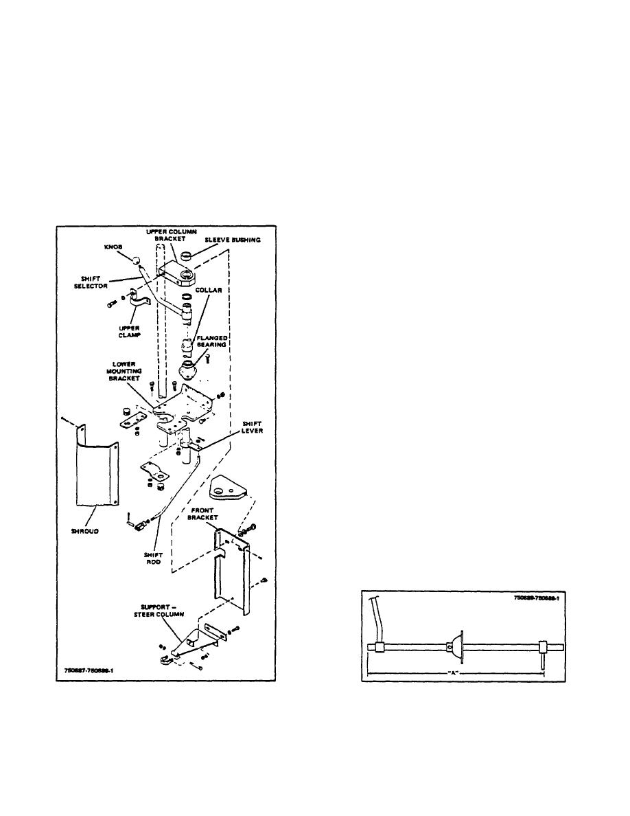
Figure 3-1. Forward-Reverse Lever Assembly
Figure 3-2. Shift Lever Dimension
2-56
|
|
Privacy Statement - Press Release - Copyright Information. - Contact Us |
