 |
|||
|
|
|||
|
Page Title:
TOPIC 1. GENERAL DESCRIPTION |
|
||
| ||||||||||
|
|
 TM 10-3930-644-14&P
TOPIC 1. GENERAL DESCRIPTION
Allis-Chalmers Lift Trucks are designed to function in a
located in each drive wheel. The parking brake is
variety of heavy-duty industrial applications. Power
mounted on the differential case, and the brake drum is
requirements are met by a gasoline, 4- or 6- cylinder,
mounted on the differential drive pinion flange. The
4-stroke cycle, naturally aspirated engine.
Engine
parking brake handle is located within easy reach of the
cooling is accomplished by a belt-driven centrifugal
operator's left hand.
pump that forces coolant through the head, block and
fin-type radiator. The engines are pressure lubricated to
A power steering control unit located at the lower end of
the rocker arms, main bearings, and connecting rods by
the steering column diverts hydraulic oil, under pressure,
a gear type oil pump driven by the camshaft. The oil is
to the appropriate power steering part. Hydraulic oil
cleaned by a replaceable oil filter. An oil filler cap is
lines connect the steering unit to the power steering
located on a filler tube assembly on the side of the
cylinder to give the lift truck a full power steering system.
cylinder block or on the valve cover. Oil level is easily
The power steering system provides maximum control of
checked by a conveniently located dipstick.
the lift truck with minimum steering effort.
The power shift transmission consists of three major
The lift assembly utilizes special rolled steel channel
components
a
constant-mesh
transmission,
a
sections, and/or "I" beams, and cross braces, all welded
hydraulically actuated clutch pack, and a torque
to form a rigid permanent structure. Due to construction
converter. A single-lever shift control on the right side of
features of the inner mast and carriage rollers, sliding
the steering column controls the direction of travel
friction is virtually eliminated.
Two independent lift
through a control valve mounted on the transmission
chains are used for safety; each has sufficient strength
housing.
to safely handle a full load. A special seat at the bottom
of the mast permits self-alignment of the lift cylinder
The drive unit incorporates a double-reduction gear train
within the mast channels, thus reducing off center
using the latest advancements in gear design. All parts
stresses.
of the unit are bearing mounted for the greatest possible
efficiency and quietness. The first reduction is through a
The heavy-duty welded steel fork carriage provides the
heavy-duty spiral bevel ring gear and pinion drive gear.
ultimate in strength and visibility. The forks are identical
Final reduction is obtained through a pinion (Jackshaft)
and interchangeable. Notches spaced along the upper
and Internal tooth gear (bull gear). This method greatly
edge of the carriage act in conjunction with latches on
reduces torque stress on the axle shaft.
the forks to position and secure then to the carriage.
The truck is equipped with hydraulic brakes designed for
Hydraulic Pressure, used to actuate the cylinders or
long life and minimum maintenance. They have a large
accessory equipment, is supplied by a positive-
braking area and give smooth braking and positive
displacement gear pump coupled
control under all operating conditions. Brakes are
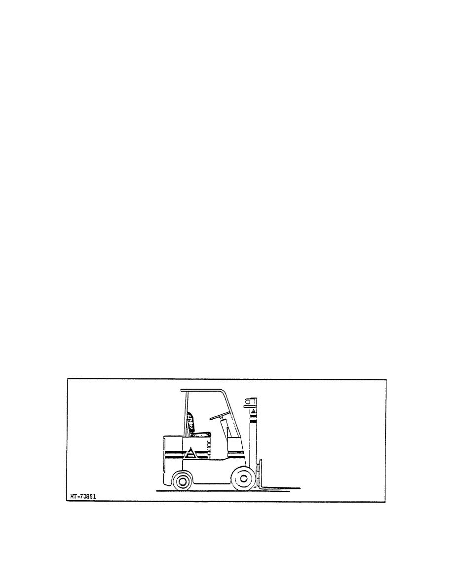
Figure 1-1. Lift Truck - Typical
1-1E
|
|
Privacy Statement - Press Release - Copyright Information. - Contact Us |
