| |
TM 10-3930-643-34
GENERAL SUPPORT BRAKE MAINTENANCE.
17-1.
Power Cluster (S/N 2000 and below and
ASSEMBLY
25.
26.
27.
28.
29.
30.
31.
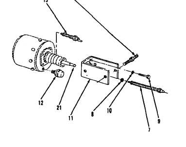
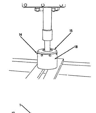
Position head (15) on shell (18).
Secure head (15) and shell (18) in
press.
Using a 9/16” socket and socket
wrench handle, install eight
screws
(14).
Using a 9/16” open end wrench,
install switch (13) and breather
(12).
Using a 9/16” socket and socket
wrench handle, install support (11),
three lock washers (10) and bolts
(9).
Install lock washer (8) and stroke
indicator (7) until
contact
with
piston assembly (21) is made. Piston
assembly (21) must be in a
relaxed
position.
Measure length of stroke indicator
(7) rod extending past nut when
piston assembly (21) iS relaxed in
shell (18).
2904 and above). (Sheet 6 of 7)
Go to sheet 7
17-7
|