| |
TM 10-3930-643-34
GENERAL SUPPORT PROPELLER AND PROPELLER SHAFTS MAINTENANCE. (cont)
16-1.
Front Differential Carrier Assembly.
ASSEMBLY (cont)
82.
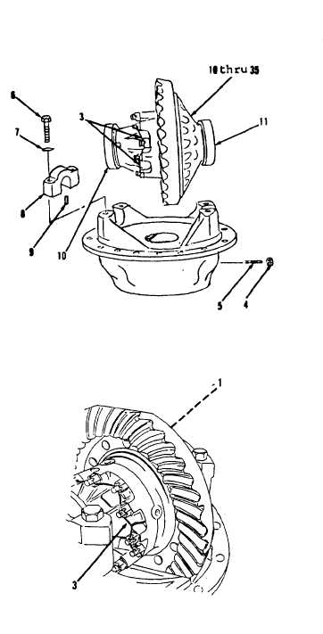
Install cups (11 and 10) on
differential assembly.
83.
Using hoist and sling, position
items 10 thru 35 as an assembly to
carrier (51).
84.
Install two adjustment rings (2).
Hand turn against cups (11 and 10).
85.
Install two pins (9), bearing caps
(8), four washers (7) and bolts (6).
Tighten bolts (6) to 160 to 190 lb-ft
torque.
Identification marks on
bearing caps and carrier must be
alined during installation. If
bearing caps do not seat properly,
check adjustment rings (2) for cross
threading.
86.
Using a 15/16” socket and socket
wrench handle, install screw (5) and
nut (4).
NOTE
The following is a difference
between M10A Forklift models.
87.
Using long round nose pliers, install
cotter pin (1) and on vehicles S/N
2000 and below and 2904 and above,
install two new lockwires (3).
ADJUSTMENT
88.
Refer to paragraph 16-3 for
differential assembly adjustment
procedures.
NOTE
Return M10A Forklift to original
equipment condition.
(Sheet 13 of 13)
GO to sheet 14
END OF TASK
16-14
|