| |
TM 10-3930-643-34
GENERAL SUPPORT PROPELLER AND PROPELLER SHAFTS MAINTENANCE.
16-1.
Front Differential Carrier Assembly.
ASSEMBLY (Cont)
NOTE
The following is a difference
between M10A Forklift models.
75.
Be sure to aline identification marks
on cases (15 and 34).
Using a 1/2”
socket and socket wrench handle,
install case (15) with four equally
spaced bolts (14) on vehicles S/N 2001
to 2903 or case (15), 16 washers (13)
and bolts (12) on vehicles S/N 2000
and below and 2904 and above.
76.
Check assembly for free rotation of
differential gears.
77.
Install remaining bolts (14) and
washers (13) or bolts (12).
Tighten
bolts (13 or 12) to 105 to 135 lb-ft.
78.
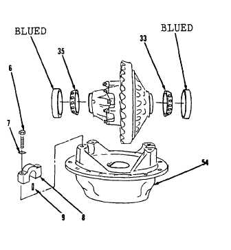
Install bearings (33 and 35) on
differential carrier and lubricate
with gear oil.
79.
Using a 15/16” socket and torque
wrench, install blue cups, two pins
(9), bearing caps (8), four washers
(7) and bolts (6) to carrier (54).
Tighten bolts (6) to 160 to 190 lb-ft.
Identification marks on bearing caps
and carrier must be alined during
installation.
80.
Check fit of cups in bearing cap
bores.
Cups must be a hand push fit.
If cups are too tight, bores must be
reworked with emery cloth until push
fit is obtained.
A blued cup should
be used as a gage to check fit.
81.
Remove four bolts (6), washers (7),
two bearing caps (8), pins (9) and
blued cups.
(Sheet 12 of 13)
GO to sheet 13
16-13
|