| |
TM 10-3930-643-34
ENGINE, FUEL, EXHAUST AND COOLING
4-4.
Cylinder Head Assembly with
TROUBLESHOOTING AND MAINTENANCE. (cont)
Valves. (Sheet 10 of 18)
DISASSEMBLY/CLEANING/INSPECTION (cont)
32.
Recheck valve face contact with
Prussian blue if valve seats are
resurfaced.
33.
Place valves in proper guides and
position dial indicator against stem.
Raise valve approximately 0.5 inches.
Move valve against and away from dial
indicator parallel to cylinder
head
(6).
NOTE
If total indicator reading is more
than 0.004 inches, send
cylinder
head to General Support.
34.
Check valve seat for correct width,
as shown.
If necessary, correct
width by grinding top edge of
valve
seat with a stone of smaller
angle
(preferably 15 degrees) than valve
seat.
NOTE
If valve does not seat properly
after resurfacing
valve
seats,
cylinder head must be
sent to
General Support.
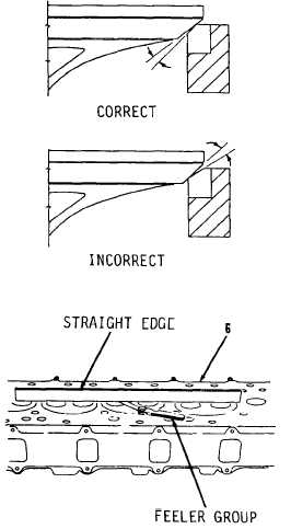
35.
Insert valves in cylinder head
(6).
Invert cylinder head (6).
Place
straight edge across valves.
Measure
distance from valves
to straight
edge.
Distance should be 0.000 to
0.014 inches. If necessary, grind
seat to different angle
to obtain
correct distance.
Go to sheet 11
4-38
|