| |
TM 10-3930-643-34
GENERAL SUPPORT ENGINE, FUEL, EXHAUST AND COOLING MAINTENANCE.
13-14.
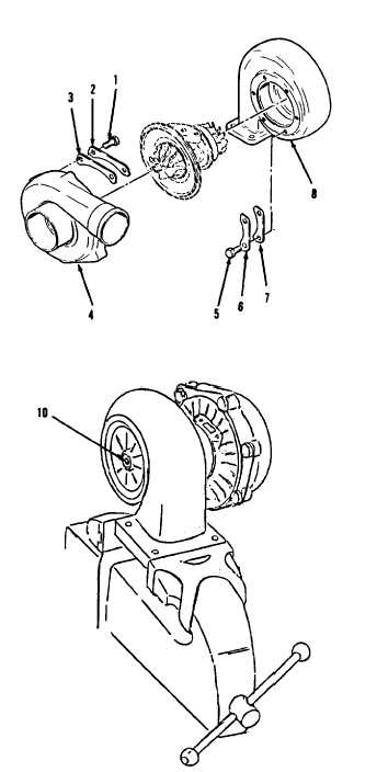
Turbocharger. (Sheet 10 of 10)
ASSEMBLY
52.
53.
54.
55.
56.
57.
58.
59.
NOTE
Aline punch marks on turbine
housing and center housing and
well as on compressor housing and
center
housing
during
installation.
Install turbine housing (8).
Coat bolt threads with anti-seize
compound. Using a 1/2” socket and
torque wrench, install three clamps
(7), lockplates (6) and six bolts
(5).
Tighten bolts (5) to 100 to 130
in-lb.
Bend tabs on lockplate (6) to secure
bolts (5).
Install compressor housing (4).
Using a 1/2” socket and socket wrench
handle, install three clamp plates
(3), lockplates (2) and six bolts
(l).
Push wheel assembly (10) shaft as far
as possible from turbine end.
Rotate wheel assembly (10) shaft and
check for binding.
Wheel assembly
(10) shaft must rotate freely without
interference.
Push as far as
possible from compressor end.
Rotate wheel assembly (10) shaft and
check for binding.
NOTE
. If turbocharger is not
to be
installed immediately, lubricate
internally and install protec-
tive covers on all openings.
. Return M10A Forklift to original
equipment condition.
END OF TASK
13-95
|