| |
GENERAL SUPPORT
13-8.
Pistons,
TM 10-3930-643-34
ENGINE, FUEL, EXHAUST AND COOLING MAINTENANCE.
Connecting Rods and Connecting Rod Bearings. (Sheet 7 of 12)
CLEANING/INSPECTION
14•
Inspect piston (5) for scuffed or
scored skirts, cracked or worn piston
lands.
Check pin bore for wear and
cracks, replace if necessary.
15.
Using a feeler gage, measure running
clearance between piston (5) and
cylinder sleeve, replace piston
(5)
if necessary.
Measure piston (5) at
a 90 degree angle from the piston pin
(10).
Clearance should be between
0.0045 and 0.0075 inches, refer to
paragraph 13-3.
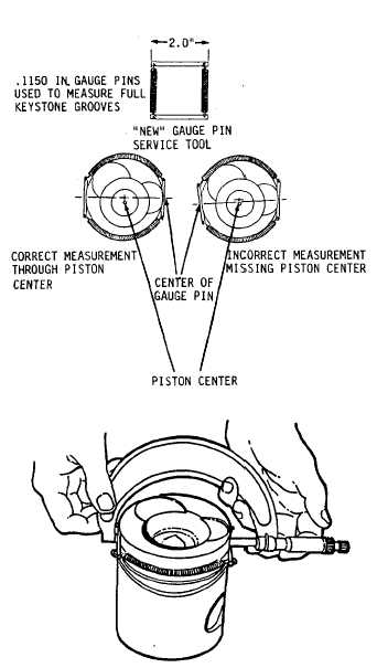
NOTE
Full keystone grooves use the
0.1150 inch gage pins to determine
piston ring groove wear. Be sure
that the center of the gage
pins
aline with the center of
the
piston so that gage pins are
parallel. Rectangular grooves do
not use gage pins.
Use side
clearance
and ring gap to
determine piston ring groove wear.
16.
17.
18.
19.
Install tool 3020 in the top of
piston (5) ring groove.
Using 4-5 inch micrometer, measure
piston (5)
over gage pins, if
necessary.
Repeat steps
16 and 17 for
intermediate ring (7) and ring (8).
For ring (7), upper limit is 4.3168
inches and replacement limit is
4.2844 inches. For ring (8), side
clearance must be between 0.002 and
0.004 inches.
Remove tool 3020 from piston (5) ring
groove.
Go to sheet 8
13-55
|