| |
TM 10-3930-643-34
ENGINE, FUEL, EXHAUST AND COOLING TROUBLESHOOTING AND MAINTENANCE. (cont)
4-2.
Engine Assembly. (Sheet 2 of 10)
REMOVAL
1.
2.
3.
4.
5.
6.
7.
NOTE
Tag all hose and tube assemblies
before disconnecting to aid in
installation.
All wire must be
tagged
when
removed
from
connector.
Indicate whether wire is
connected
to pin-type or
socket-type connector.
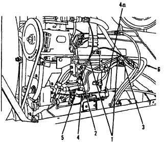
Cut and discard two tie straps (1)
from right side of engine (38).
Using a 7/16” open end wrench,
disconnect hose assembly (2) from
air governor and move to one side,
away from engine assembly.
Using 1" and 3/4” open end wrenches,
disconnect hose
assembly (3) at
adapter and move to one side,
away
from engine assembly.
Using long round nose pliers,
disconnect spring (5) from bracket on
fuel pump cover.
Using a 7/16” socket, socket wrench
handle and a 7/16” open end wrench,
disconnect cable (4) from injection
pump arm and mounting bracket.
Using a 15/16” open end wrench, loosen
two nuts (4a) and remove cable (4) from
mounting bracket and lay away from
engine.
Using an 11/16” open end wrench, dis-
connect tube assembly (6) from rear of
engine assembly.
Go to sheet 3
4-16
|