| |
TM 10-3930-643-34
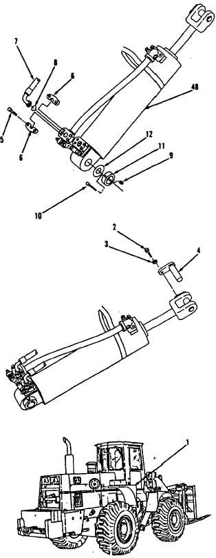
Position hoist and sling on cylinder
assembly (48), making sure the sling
is rapped under
tube assembly (19)
and take up slack.
Coat mounting rod on lower frame of
vehicle with grease.
Using a hoist and sling, install
cylinder assembly (48) on vehicle.
Using a 3/4” socket, socket wrench
handle and open end wrench, install
shim (12), fitting (11), bolt (10)
and nut (9) to lower end of cylinder
assembly (48).
Install two new preformed packings
(8).
Connect two hose assemblies (7).
Using a 9/16”
socket and socket
wrench handle, install four flanges
(6) and eight bolts (5) on hose
assemblies (7).
Start engine
and move lift control
lever to RAISED position to aline rod
(45) with boom assembly.
Using a 1-1/8”
socket and socket
wrench handle, install pin (4),
washer (3) and bolt (2) in rod end of
cylinder assembly (48).
HYDRAULIC SYSTEM TROUBLESHOOTING AND MAINTENANCE.
12-12.
Lift Cylinder. (Sheet 9 of 10)
INSTALLATION
53.
54.
55.
56.
57.
58.
59.
60.
61.
62.
Remove hoist and sling.
63.
Install fender (1) to front, right
side of vehicle, refer to TM 10-3930-
643-12.
64.
Lubricate grease fittings, refer to
TM 10-3930-643-12.
Go to sheet 10
12-109
|