| |
TM 10-3930-643-34
HYDRAULIC SYSTEM TROUBLESHOOTING AND MAINTENANCE.
12-6.
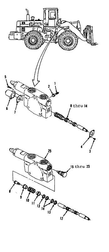
Tilt Valve Assembly. (Sheet 2 of 8)
DISASSEMBLY
1.
2.
3.
4.
5.
6.
7.
8.
Remove spring (1) and poppet (2).
Using a flat tip screwdriver, remove
two screws (3) and plate (4).
Using a 1/4”
socket head screw key,
remove two bolts (5), cap
(6) and
plate (7).
Remove items 8 thru 15 as an
assembly. Note position of spool
(13) to aid in installation.
Using a flat tip screwdriver, remove
screw (8).
Remove seat (9), spring (10) and
seat (11) from spool (12).
Using a machinists scribe, remove
and discard two wipers (13) and seals
(14).
Using a 1-1/4” socket and socket
wrench handle, remove items 15 thru
23 as an assembly from housing (25).
Go to sheet 3
12-43
|