| |
TM 10-3930-643-34
HYDRAULIC SYSTEM TROUBLESHOOTING AND MAINTENANCE. (cont)
12-3.
Loader Control Valve. (Sheet 8 of 14)
TESTING/ADJUSTING - RELIEF VALVES
34.
35.
36.
37.
38.
39.
40.
41.
42.
43.
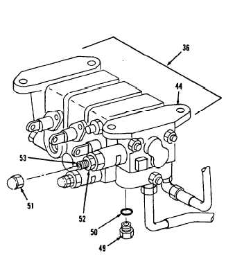
44.
Vent hydraulic system, refer to
TM 10-3930-643-10.
Using a 11/16” socket and socket
wrench handle, remove plug (49) and
preformed packing (50) from loader
control valve (36) and inlet
valve
assembly (44).
Discard preformed
packing (50).
Using a 10” adjustable wrench,
install 3000 psi hydraulic
pressure
gage in plug (49) port.
Start engine in operator’s compart-
ment.
Operate tilt and fork controls
through four loading cycles, refer to
TM 10-3930-643-10.
Position forks in
forks together
position and hold, refer to TM 10-
3930-643-10.
Accelerate engine to full throttle.
Read hydraulic pressure gage. If
system does not relieve at 2755 psi,
adjust system relief valve.
Using a 1-1/4” and 11/16” open end
wrenches, remove system relief valve
and acorn nut (51) from loader
control valve (36) and inlet valve
assembly (44).
Using a 3/4” open end wrench, loosen
jam nut (52).
Using a flat tip screwdriver, adjust
screw (53), turning
clockwise to
increase
the
pressure
and
counterclockwise to
decrease
pressure.
Go to sheet 9
12-20
|