| |
TM 10-3930-643-34
STEERING TROUBLESHOOTING AND MAINTENANCE.
9-6.
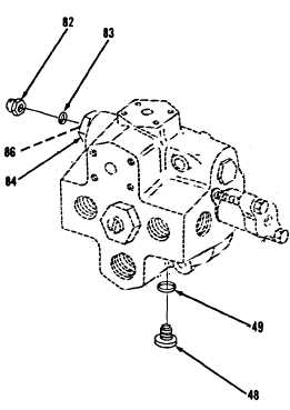
Control Valve and Check Valve. (Sheet 15 of 15)
ADJUSTMENT
103.
104.
105.
106.
107.
108.
109.
110.
111.
112.
Using an 11/16" socket and socket
wrench handle, remove nut (82) and
preformed packing (83).
Discard
preformed packing (83).
Loosen locknut (84).
Using a flat tip screwdriver, back
off adjusting screw (86) until no
tension is felt.
Start engine and run at high idle.
Turn steering wheel fully right or
left.
Hydraulic fluid must be at
normal
operating
temperature.
Pressure gage should read 2000 psi.
Using a flat tip screwdriver, turn
adjusting screw (86) clockwise to
increase pressure, counterclockwise
to decrease pressure, as necessary.
Using an 11/16" socket, socket
wrench handle and
torque
wrench,
tighten locknut (84) to 10 lb-ft.
Stop engine.
Install new preformed packing
(83)
and nut (82).
Remove hydraulic pressure gage.
Using a 5/8" socket, socket wrench
handle and torque wrench,
install
new preformed packing (49) and
one
plug (48).
Tighten plug (48) to 30
lb-ft.
NOTE
Return M10A Forklift
equipment condition.
to original
END OF TASK
9-51
|