| |
TM 10-3930-643-34
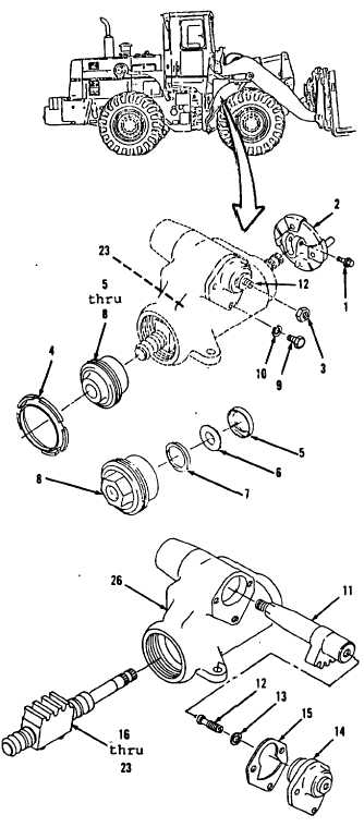
STEERING TROUBLESHOOTING AND MAINTENANCE.
9-2.
Steering Gear Assembly. (Sheet 2 of 8)
DISASSEMBLY
NOTE
Scribe a mark on flange and shaft
of ballnut and worm assembly to
aid in installation.
1.
2.
3.
4.
5.
6.
7.
8.
9.
Using a 9/16” open end wrench, remove
bolt (1) and flange (2).
Using a 3/4” socket and socket wrench
handle, remove nut (3).
Turn setscrew (12) counterclockwise
several times to relieve load
from
bearings (6 and 23).
Using a spanner wrench,
remove
locknut (4) and items 5 thru 8 as an
assembly.
Using a cotter pin extractor, remove
seat (5), bearing (6) and ring
(7)
from adjuster (8).
Using a 9/16” socket and socket
wrench handle, remove
three bolts
(9), washers (10) and items 11 thru
15 as an assembly.
Using a large rubber mallet, remove
gearshaft (11).
Using a flat tip screwdriver, remove
setscrew (12), shim (13) and gasket
(15) from cover (14). Discard gasket
(15).
Using a large rubber mallet, remove
items 16 thru 23 as an assembly from
housing (26).
GO to sheet 3
9-7
|