| |
TM 10-3930-643-34
GENERAL MAINTENANCE PROCEDURES.
2-13.
Electrical Repairs.
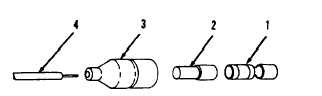
(7) Connector, terminal-type, weather-proof.
DISASSEMBLY
1.
Slide shell (3) back to expose sleeve (2).
2.
Slide sleeve (2) back to expose terminal (1).
3.
Remove and discard terminal (1).
4.
Remove sleeve (2) and shell (3).
ASSEMBLY
1.
2.
3.
4.
5.
6.
7.
Strip wire (4), refer to Wire Size Chart. Do not nick or cut strands.
Tin bare wires. Use resin-core solder to coat bare wires.
If using
solid core solder, clean wires
Slide shell (3) and sleeve (2)
New terminal must be selected to
at the terminal connection. New
with flux before tinning.
onto wire (4).
NOTE
match the size of the mating contact
terminal must also match the crimping
area with the thickness of the wire.
Strip wire (4), refer to Wire Size Chart. Do not nick or cut strands.
Tin bare wires. Use resin-core solder to coat bare wires.
If using
solid core solder, clean wires with flux before tinning.
Insert wire (4) into new terminal (1).
NOTE
Connector sleeve and shell are held in position over terminal by
compression. Sleeve must be firmly seated on terminal and shell must
be firmly seated over sleeve.
Slide shell (3) over sleeve (2) and terminal (1).
2-23
|