| |
TM 10-3930-643-34
BRAKE TROUBLESHOOTING AND MAINTENANCE. (cont)
8-14.
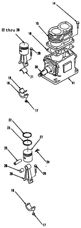
Air Compressor. (Sheet 3 of 13)
DISASSEMBLY (cont)
7.
8.
9.
10,
11.
12.
13.
14.
15.
16.
17.
Using a drift punch and hammer,
matchmark cylinder block
(15) and
crankcase (41) with punch.
Using a 1/2” open end wrench, remove
six lock bolts (14), cylinder block
(15) and gasket (16) from crankcase
(41).
Discard gasket (16).
Lift cylinder block (15) straight up
until clear of pistons.
Position crankcase (41) on one side.
Rotate crankshaft (38) to bring one
connecting rod (26) to bottom of
stroke.
Using a 1/4” socket, socket wrench
handle and a open end wrench, remove
two locknuts ((17), rod cap (18),
bearing half (19), two bolts (20),
items 22 thru 28 as an assembly and
bearing half (21). Discard bearing
halves (19 and 21).
Repeat procedure
for
second
connecting rod and piston assembly.
Replace two rod caps
(18) on
connecting rods (26).
Using a 1/4” socket and socket wrench
handle, install four bolts (20) and
locknuts (17).
Identify connecting rods (26) as
matched assemblies by marking with
quick dry paint.
Using a small flat tip screwdriver,
remove ring sets (22 and
23) from
connecting rod and piston assembly.
Go to sheet 4
8-64
|