| |
TM 10-3930-643-34
ENGINE, FUEL, EXHAUST AND COOLING
4-14.
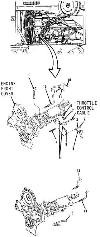
Fuel Injection Pump, Cover
REMOVAL
Before performing injection
TROUBLESHOOTING
Plate, Adapter
AND MAINTENANCE. (cont)
and Drive Gears. (Sheet 2 of 9)
pump
removal procedure, rotate engine
clockwise until the No. 1 piston
is on compression
stroke
and
timing pointer is at 15 degrees
BTDC plus or minus 1 degree.
If the pump is to be reinstalled,
DO NOT rotate the pump drive shaft
after the pump has been removed.
Thoroughly clean left side of
engine to prevent dirt from
entering pump.
Be sure to plug all
openings of pump and lines to
prevent entry of dirt.
Failure to observe the preceding
can result in severe damage to
engine or fuel injection pump.
NOTE
Tag all hose and tube assemblies
before disconnecting to aid in
installation.
1.
Using a
3/4“
open
end
wrench,
disconnect six fuel injector lines
(1) from right side of engine.
3*
Using a flat tip screwdriver, remove
nut (2), washer (3) and terminal (4).
3.
Using long round nose pliers, a 7/16”
socket and a 7/16” open end
wrench,
remove spring (5), nut (6), washer
(7), bolt (8) and two washers (9).
4.
Using a 9/16” socket and socket
wrench handle, remove bolt (10), lock
washer (11) and washer (12).
Leave
clip attached to tube assembly (13).
5.
Using a 3/4” open end wrench,
disconnect tube assemblies (13, 14,
15 and 16).
Go to sheet 3
4-94
|