| |
TM 10-3930-643-34
ENGINE, FUEL, EXHAUST AND
4-6.
Rocker Arm Assembly
ADJUSTMENT
COOLING TROUBLESHOOTING
and Valve Cover. (Sheet
28.
Using a flat tip screwdriver, a 9/16”
open end wrench and a feeler gage,
adjust rocker arm numbers 1, 2, 3, 6,
7 and 10 in top of engine, refer to
Valve Lash Adjustment Chart.
29.
Turn crankshaft on bottom, rear of
engine until No. 6 piston is at TDC
(compression) which is one complete
revolution of vibration damper,
30.
Adjust rocker arm numbers 4, 5, 8, 9,
11 and 12, refer to Valve Lash
Adjustment Chart.
31.
Using a flat tip screwdriver, a 9/16”
open end wrench and a feeler gage,
tighten 12 nuts (26) to 20 lb-ft.
NOTE
If valve are in correct adjustment,
proceed to installation.
INSTALLATION
32.
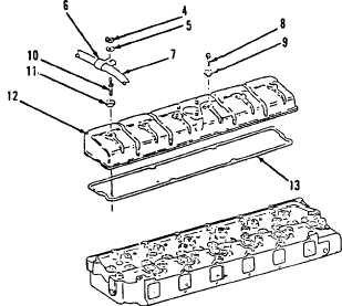
Using a 1/2” socket and socket wrench
handle, install new gasket (13),
access cover (12), new preformed
packing (11), stud (10), five new
preformed packing (9) and bolts (8).
Tighten bolts (8) and stud (10) to 26
lb-ft.
33.
Position hose assembly (7) and using
a 1/2” socket and socket wrench
handle, install clamp (6), washer (5)
and nut (4).
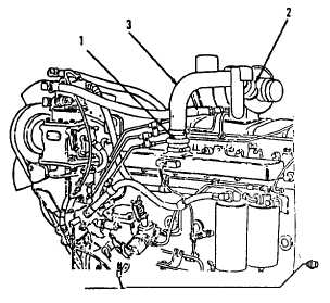
34.
Install tube assembly (3).
35.
Using a flat tip screwdriver, tighten
clamps (2 and 1).
NOTE
AND MAINTENANCE.
9 of 9)
Return M10A Forklift to original END OF TASK
equipment condition.
4-59
|