| |
TM 10-3930-643-20
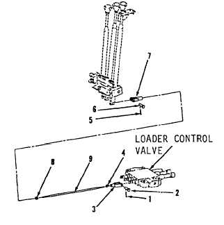
HYDRAULIC SYSTEM TROUBLESHOOTING AND MAINTENANCE. (cont)
14-3.
Fork Control Lever Assemblies. (Sheet 7 of 7)
ADJUSTMENT
46.
47.
48.
49.
50.
51.
52.
Position fork control lock in cab
f l o o r , c e n t e r r i g h t.
P o s i t i o n d e t e n t s o f f o r k c o n t r ol
valve in neutral.
Using a 1/2” open end wrench, loosen
nuts (4 and 8).
Position clevises (3 and 7) apart to
the measurement
taken
before
removal.
Using a 1/2” open end wrench,
tighten nuts (4 and 8).
Start engine.
Operate
three-movement
c o n t r ol
l e v e r . C h e c k f o r p r o p e r o p e r a t i on
and adjust as needed.
NOTE
Return M10A Forklift to orginial
equipment condition.
END OF TASK
14-14
|