| |
TM 10-3930-643-20
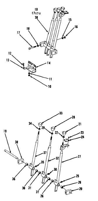
HYDRAULIC SYSTEM TROUBLESHOOTING AND MAINTENANCE. (cont)
14-3.
Fork Control Lever Assemblies. (Sheet 3 of 7)
REMOVAL (cont)
7.
Using a 3/4” socket and a 3/4”
combination wrench, remove two nuts
(10), washers (11), screws (12),
washers (13) and hinge (14) from
center right of cab floor.
8.
Using two 9/16” combination
wrenches, remove two nuts (15),
washers (16), screws (17), washers
(18) and items 19 thru 38 as an
assembly.
DISASSEMBLY
9.
Remove pin (19) and bar (20).
10.
Remove bar (38).
11.
Using a 9/16” open end wrench,
loosen nut (22).
12.
Remove knob (21) and nut (22).
13.
Using a flat tip screwdriver, remove
four drive screws (23) and decal
( 2 4 ).
14.
Using a 7/16” open end wrench,
remove fitting (25).
15.
Remove two bearings (26) from lever
( 2 7 ).
16.
Using a 9/16” open end wrench,
loosen nut (29).
17.
Remove knob (28) and nut (29).
18.
Using 7/16” open end wrench, remove
f i t t i n g ( 3 0 ) .
19.
Remove two bearings (31) from lever
( 3 2 ) .
20.
Using a 9/16” open end wrench,
loosen nut (34).
Go to sheet 4
14-10
|